Liquid level sensor

Inactive Publication Date: 2002-09-19
THERM O DISC
View PDF0 Cites 59 Cited by
  • Summary
  • Abstract
  • Description
  • Claims
  • Application Information

AI Technical Summary

Benefits of technology

0002] There exists a wide variety of applications in which it is desirable to monitor to some degree the level of a liquid within a vessel or the like. Such applications may range from monitoring various fluid levels within a motor vehicle or internal combustion engine or fuel tank to monitoring oil levels within a pump or compressor or even water levels within a tank such as for a recreational vehicle or boat. In each of these applications it is desirable that the liquid level sensor be capable of providing a reliable accurate indication of the liquid level over an extended period of time without requiring periodic maintenance. In many applications the level sensor must be capable of enduring various levels of vibration, heat or other hostile environmental elements as well as space limitations. Additionally, in some applications utilizing sealed vessels such as hermetic compressors, it is desirable to minimize the number of penetrations such as electrical leads through the walls of the vessel to reduce the potential for leakage.
0003] Various types of devices have been developed over the years for sensing such levels of liquids. Such devices range from the extremely simple float arrangement commonly employed in fuel tanks to more complex electrical capacitance type sensors as well as microprocessor based thermocouple sensors. While operable, these various types of sensors have had varying drawbacks depending upon the particular application such as excessive space requirements for accommodating moveable floats and associated linkage, relatively high costs to manufacture, complexity of circuitry required to generate a level ind

Problems solved by technology

While operable, these various types of sensors have had varying drawbacks depending upon the particular application such as excessive space requirements for accommodating moveable floats and associated linkage, relatively hig

Method used


Image

  • Liquid level sensor
  • Liquid level sensor
  • Liquid level sensor

Examples


Embodiment Construction

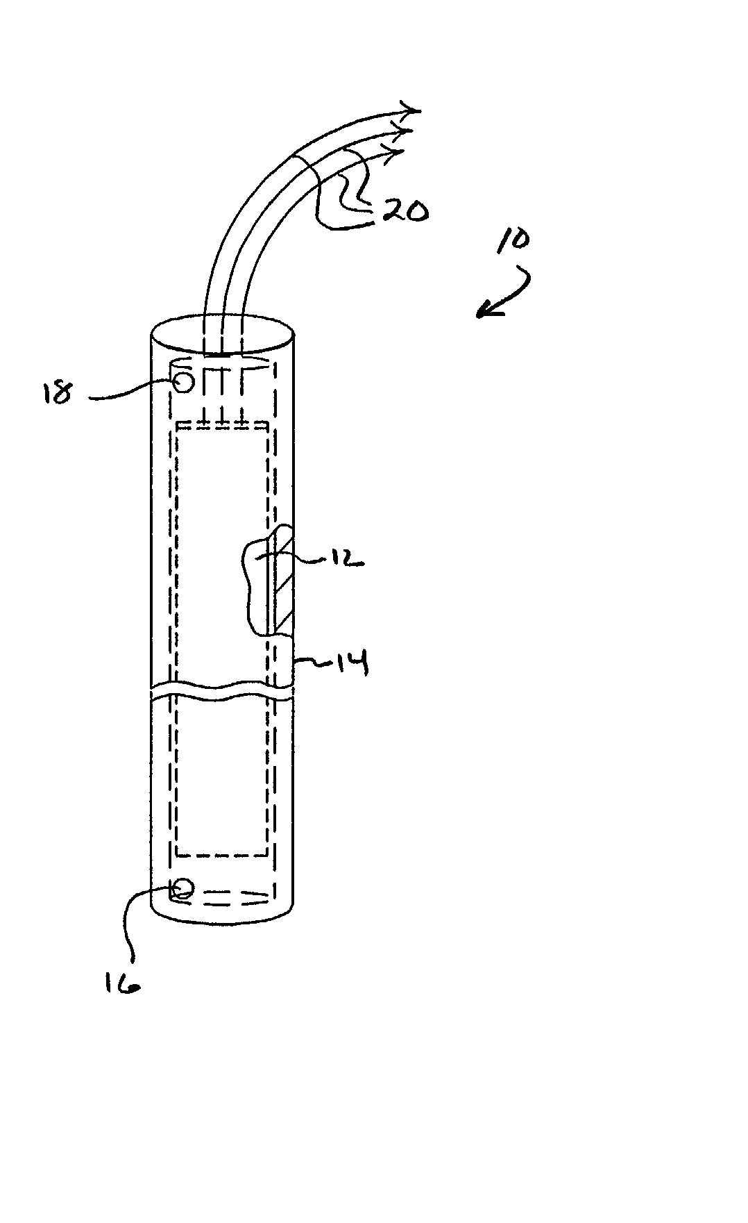
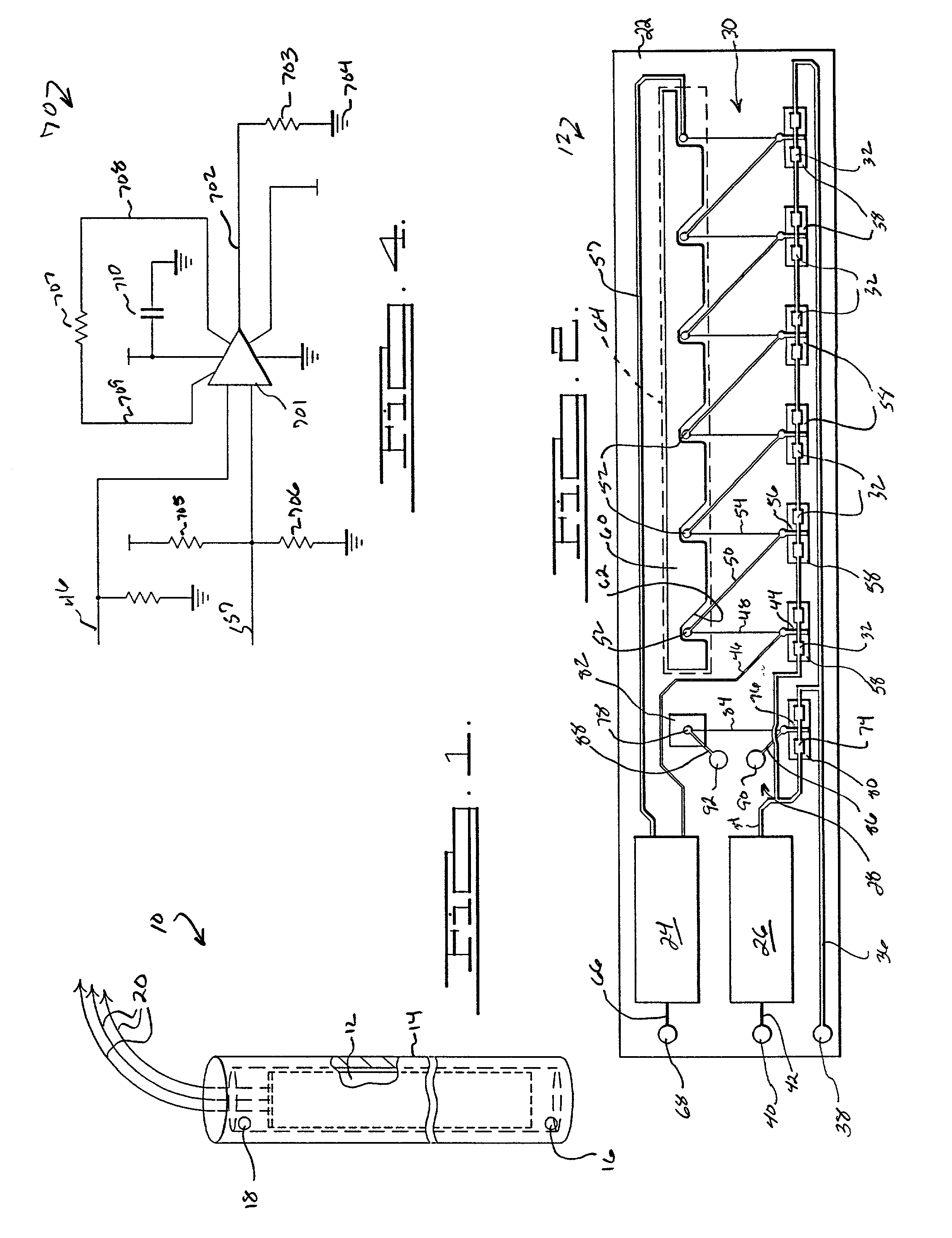
[0015] Referring now to the drawings and in particular to FIG. 1, there is shown a liquid level sensor 10 in accordance with the present invention. Liquid level sensor 10 comprises a printed circuitboard 12 disposed within a hollow generally cylindrically shaped container 14. Preferably container 14 will be closed at least at the lower end thereof and will have one or more holes 16, 18 opening into the interior adjacent each end thereof. Holes 16 enable liquid to flow into or out of the interior of container 14 whereas holes 18 allow gases to flow into and out of container 14. As shown, a plurality of leads 20 extend outwardly from circuitboard 12 through the upper end of container 14. Container 14 serves to dampen the changes in liquid level which may occur as a result of movement of the vessel within which the liquid is contained and / or agitation of the liquid resulting from movement of apparatus within the liquid containing vessels. The specific number of holes 16 and 18 at each ...


PUM


Abstract

An improved liquid level sensor is disclosed which provides a reliable and simple device for accurately determining the level of a liquid within a vessel. The sensor of the present invention utilizes a plurality of thermocouples grouped in pairs with the pairs being spaced along a line extending generally in the direction in which the liquid level may vary. A first thermocouple of each pair is located in relatively close thermal proximity to an electrically powered heater and the second of each pair of thermocouples is spaced away from the heater. The thermocouples are connected in series and produce a signal directly indicative of the level of the liquid along the sensor. Additionally, a pressure sensing circuit may also be incorporated with the liquid level sensor.

Description

BACKGROUND AND SUMMARY OF THE INVENTION[0001] The present invention relates generally to devices used to measure the level of a liquid within a vessel or container and more specifically to such a device which employs a plurality of serially connected thermocouples arranged in laterally spaced pairs with respective thermocouples of each pair being positioned in substantially parallel spaced rows.[0002] There exists a wide variety of applications in which it is desirable to monitor to some degree the level of a liquid within a vessel or the like. Such applications may range from monitoring various fluid levels within a motor vehicle or internal combustion engine or fuel tank to monitoring oil levels within a pump or compressor or even water levels within a tank such as for a recreational vehicle or boat. In each of these applications it is desirable that the liquid level sensor be capable of providing a reliable accurate indication of the liquid level over an extended period of time w...

Claims


Application Information

Patent Timeline
IPC IPC(8): G01F15/02G01F23/24
CPCG01F15/022G01F23/246G01F23/22
Inventor ZIMMERMANN, BERNDREYNOLDS, DAVID W.WELCH, RICHARD E.MILLET, HANK E.
Owner THERM O DISC
Why Eureka
Try Eureka