
Method and apparatus for removing a liquid from a surface of a rotating substrate

a technology of rotating substrate and liquid, which is applied in the direction of photomechanical equipment, cleaning using liquids, instruments, etc., can solve the problems of incompatibility with the majority of other processes, increase the cycle time, and undesirable variables, and achieve the effect of preventing back splashing

Inactive Publication Date: 2002-09-19
INTERUNIVERSITAIR MICRO ELECTRONICS CENT (IMEC VZW)
View PDF0 Cites 17 Cited by
  • Summary
  • Abstract
  • Description
  • Claims
  • Application Information

AI Technical Summary

Benefits of technology

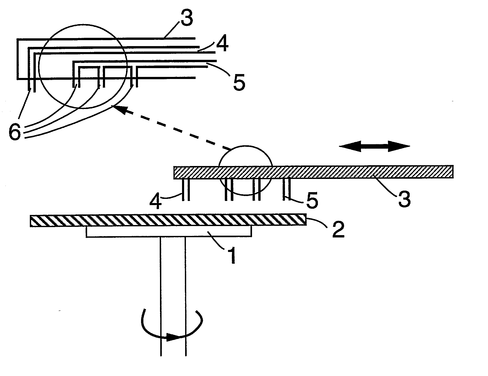
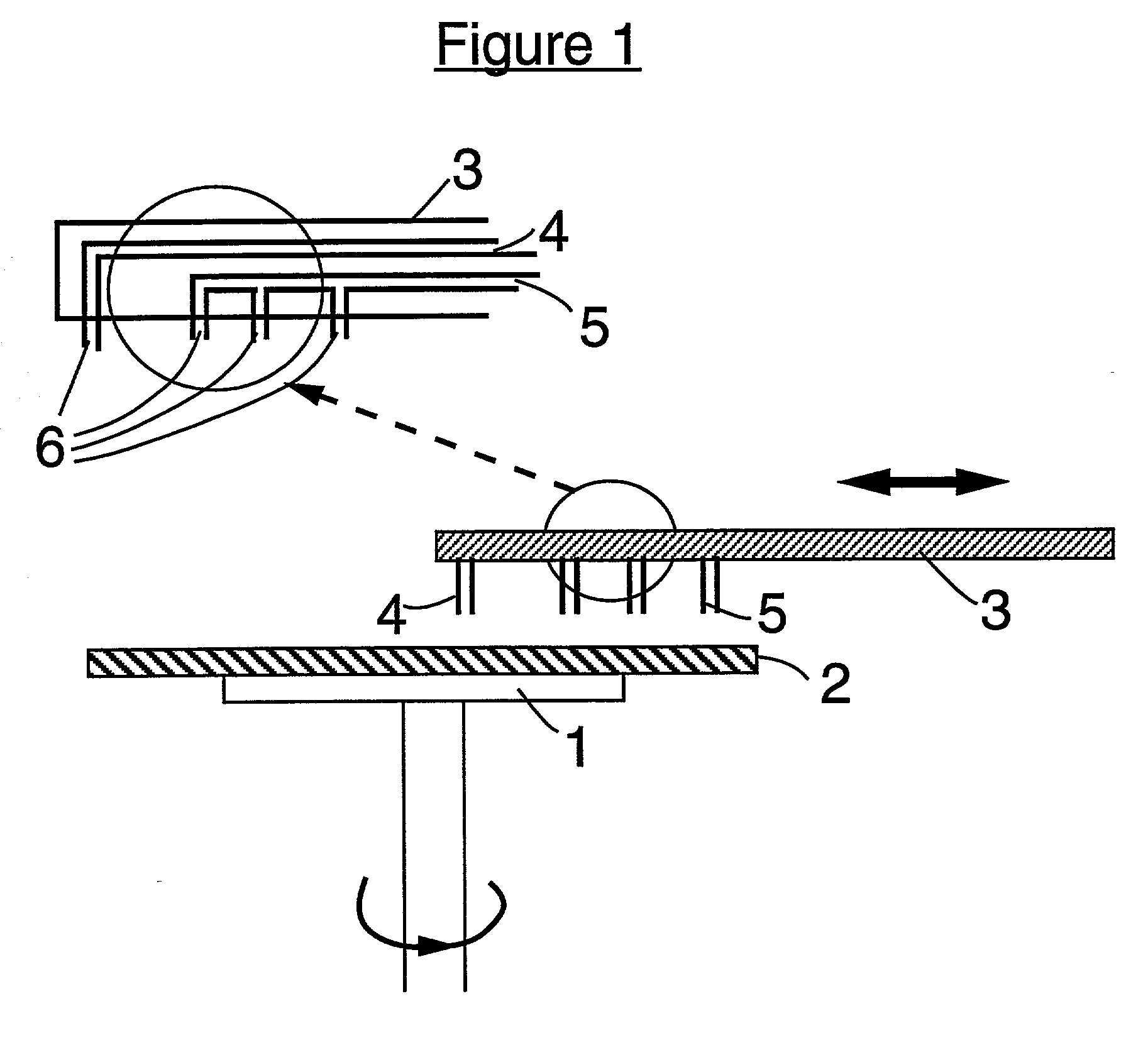
[0016] supplying a gaseous substance to said surface of said substrate while supplying said liquid, said gaseous substance being at least partially miscible with said liquid and when mixed with said liquid yielding a mixture having a surface tension being lower than that of said liquid. Particularly on at least a part of the surface of the substrate, fresh liquid is sprayed continuously. The entire surface at the liquid side of the liquid-vapor boundary can be covered, as e.g. for hydrophilic surfaces, with a continuous film of the liquid. The speed of the rotary movement is chosen such that the flow of said sprayed liquid on at least one side of the wafer is transported outwards due to the centrifugal forces. Moreover, said gaseous substance, when mixed with said liquid yields a mixture having a surface tension being lower than that of said liquid. The resulting surface tension reduction of said liquid facilitates the movement of said liquid towards an edge of the substrate. The surface left behind is cleaned and dried. It is presumed that this drying action is obtained according to at least the combination of the rotary movement and the Marangoni effect. According to the Marangoni effect said substances will be mixed with the liquid such that in the liquid meniscus, its concentration decreases in the direction of the liquid. This gradient in concentration creates an additional force exerted on the liquid film in the direction of the liquid film resulting in a good drying performance.
[0018] In another embodiment of the invention, eventually prior to the liquid removal step an etching, a cleaning or a rinsing liquid or a sequence of such liquids can be supplied to the entire surface of a rotating substrate. Particularly prior to the liquid removal step of the present invention, a liquid comprising water, ozone and an additive acting as a scavenger can be dispensed on a surface of a rotating substrate in order to remove organic contaminants from said surface. Preferably said liquid is maintained at a temperature below the boiling point of said liquid. The parameters can be optimized such that a liquid film can completely cover a surface. The spinning motion will quickly transport the liquid over the surface towards the edge, thus allowing relatively short carry-over transients and thus also allowing for relatively short rinsing times. Using such a continuously switched flow of liquids eliminates the undesirable passage of liquid-gas interfaces over the surface. The liquid removal method of the present invention is applicable for each sequence of at least one wet processing step by supplying a surface tension reducing gaseous substance together with the liquid. The drying can thus be applied directly on the processing liquid if relevant for the application. Since the proposed drying technique is found to be very fast, process non-uniformity over the surface can be kept very low.
[0020] In another embodiment of the invention, another force can be combined with the liquid removal process of the present invention. Particularly, by using megasonic energy as said other force to agitate the liquid applied during the removal process the cleaning performance of said liquid removal process can be enhanced. Doing so can help in particle reduction. Alternatively also contacting a surface with a rotating cleaning pad is an example of such other force.
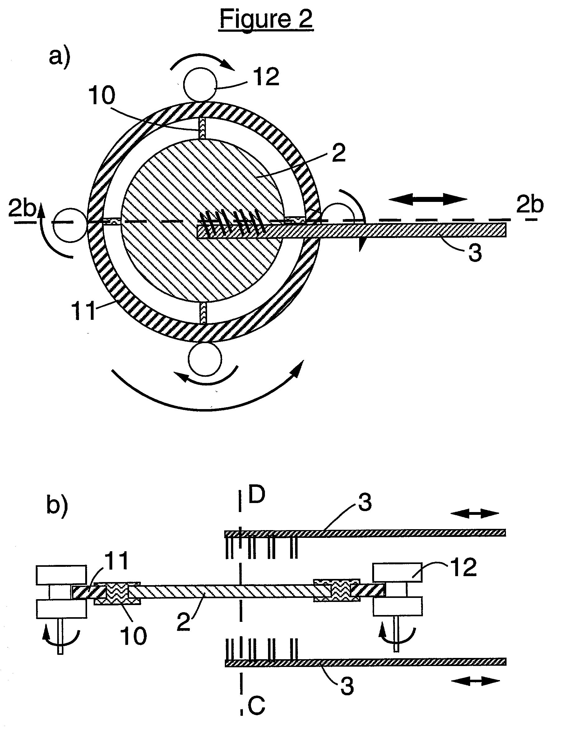
[0025] In an embodiment of the invention, said apparatus further comprises a chamber, preferably pressurizable, wherein said substrate holder is positioned. This chamber is designed in a manner to avoid back splashing of the liquid removed from a surface onto said surface. For instance, a chamber having slanted walls may be used. Particularly, the substrate holder may be positioned horizontally in said chamber. In such case, preferably the vertical walls of said chamber are oriented such that the angle between said walls and the horizontally positioned substrate holder is smaller than 90 degrees in order to prevent back splashing of the liquid which is removed according to the method of the present invention.

Problems solved by technology

On the other hand, wet processing steps such as e.g. cleaning steps and subsequent liquid removal steps are typically performed in a batch mode because of lack of appropriate alternatives.
Such variability is undesirable with regard to process control.
Moreover this mixed batch and single substrate processing increases the cycle time, which is also undesirable.
Particularly, one of the major challenges regarding single wafer wet processing is a method for removing a liquid from both sides of a substrate.
This handling is incompatible with the majority of the other process steps where the equipment and transportation tools are developed to handle horizontal positioned substrates.
It is known that such a spin-drying technique leaves undesirable residues, often referred to as drying marks, on the substrate surface, particularly on surfaces having mixed hydrophilic and hydrophobic regions.
Particularly, a disadvantage is that regardless of the precise nature of the liquid, during the liquid removal process always rinsewater is supplied.
Furthermore, the surface tension reducing vapor is passively applied, e.g. by natural evaporation, which makes it difficult to locally, i.e. at moving zone, have a good and efficient control on the vapor supply or to direct the vapor.
Moreover U.S. Pat. No. 5,660,642 does not disclose how to remove a liquid film substantially simultaneously from two opposite surfaces, i.e. top and bottomside, of a horizontally positioned substrate.

Method used


Image

  • Method and apparatus for removing a liquid from a surface of a rotating substrate
  • Method and apparatus for removing a liquid from a surface of a rotating substrate
  • Method and apparatus for removing a liquid from a surface of a rotating substrate

Examples


Embodiment Construction

[0034] In relation to the appended drawings the present invention is described in detail in the sequel. Several embodiments are disclosed. It is apparent however that a person skilled in the art can imagine several other equivalent embodiments or other ways of executing the present invention, the spirit and scope of the present invention being limited only by the terms of the appended claims.

[0035] In an aspect of the invention a method of removing a liquid from at least one surface of at least one substrate is disclosed, said method comprising the steps of:

[0036] supplying a liquid on at least a part of said surface of said substrate;

[0037] supplying a gaseous substance to said surface of said substrate, said gaseous substance being at least partially miscible with said liquid and when mixed with said liquid yielding a mixture having a surface tension being lower than that of said liquid; and

[0038] subjecting said substrate to a rotary movement. Said gaseous substance can comprise ...


PUM

PropertyMeasurementUnit
Angular velocityaaaaaaaaaa
Speedaaaaaaaaaa
Surface tensionaaaaaaaaaa

Abstract

A method and an apparatus for removing a liquid, i.e a wet processing liquid, from a surface of at least one substrate is disclosed. A liquid is supplied on a surface of substrate. Simultaneously or thereafter besides the liquid also a gaseous substance can be supplied thereby creating at least locally a sharply defined liquid-vapor boundary. The gaseous substance and the liquid can be selected such that the gaseous substance is miscible with the liquid and when mixed with the liquid yields a mixture having a surface tension lower than that of the liquid. According to the invention, the substrate is subjected to a rotary movement at a speed to guide said liquid-vapor boundary over said substrate thereby removing said liquid from said substrate.

Description

REFERENCE TO RELATED APPLICATIONS[0001] This application is a continuation-in-part of U.S. utility application Ser. No. 09 / 022,834 filed Feb. 13, 1998 and claims priority benefits to European patent application No. 988700563 filed Mar. 20, 1998, to U.S. provisional application Serial No. 60 / 059,929 filed on Sep. 24, 1997, to U.S. provisional application Serial No. 60 / 079,688 filed on Mar. 27, 1998, and to U.S. provisional application Serial No. 60 / 084,651 filed on May 6, 1998.FIELD OF THE INVENTION[0002] The present invention is related to an apparatus and a method of removing a liquid from a rotating substrate. This liquid can be any wet processing liquid, as e.g. a wet etching liquid or a cleaning liquid. It can also be a rinsing liquid. The invention is applicable for a number of wet processing steps which are frequently used in the fabrication process of integrated circuits or liquid crystal displays.BACKGROUND OF THE INVENTION[0003] The complete and efficient removal of a liqui...

Claims


Application Information

Patent Timeline
IPC IPC(8): G03F7/42H01L21/00H01L21/306H01L21/311H01L21/768
CPCG03F7/423H01L21/02046H01L21/02052H01L21/31116H01L21/31133H01L21/31138H01L21/67028H01L21/67034H01L21/67051Y10S134/902
Inventor MERTENS, PAULMEURIS, MARKHEYNS, MARC
Owner INTERUNIVERSITAIR MICRO ELECTRONICS CENT (IMEC VZW)
Learn More