
External thickness control and method

Inactive Publication Date: 2002-09-19
ADDEX DESIGN
View PDF16 Cites 19 Cited by
  • Summary
  • Abstract
  • Description
  • Claims
  • Application Information

AI Technical Summary

Benefits of technology

[0015] The present invention includes an external air ring thickness profile control system on a blown film extrusion line. The external thickness profiler of the present invention includes a simple to use and inexpensive manual actuation system as well as an automatic actuation system. Rather than trying to minimize pressure drop with an actuating zone, the system of the present invention employs a high pressure drop actuator which acts locally to alter air flow without affecting critical relative flows to lips where the air is provided to the blown film.
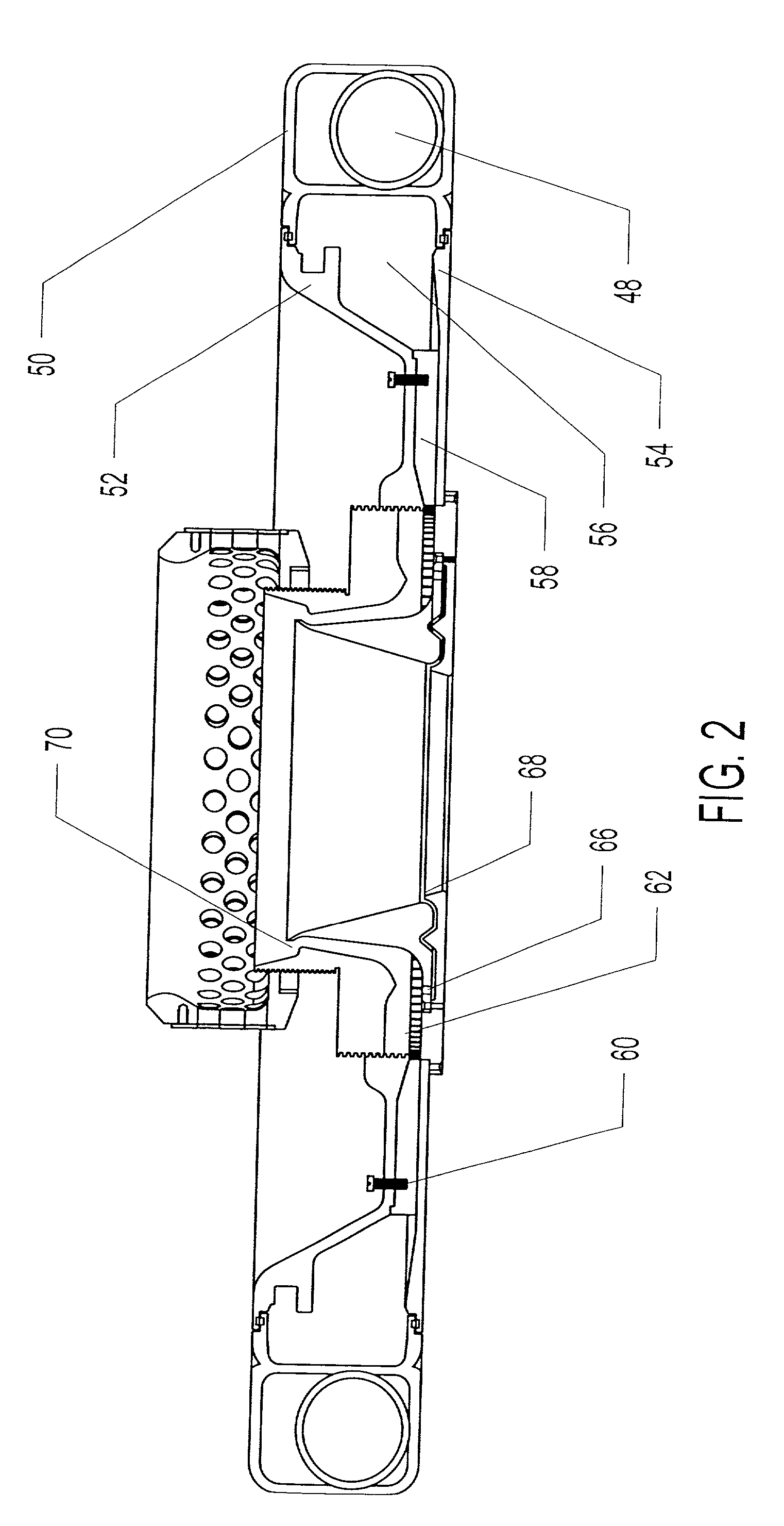
[0016] According to one embodiment of the present invention, air is provided through radial channels and then to the lips, in which case cross-sections at actuation points are varied in one or more channels to locally alter air flow such that there is a high pressure drop before reaching the lips. This drop allows the air flow to normalize within the channel after actuation and thus to develop into uniform pipe flow. Upon exiting the radially inward end of the multiple channels, the air flows are under semi-laminar flow conditions inwardly through the lip section, thus preventing appreciable mixing with air from other channels. After the actuator, the length of the radial channel should be of sufficient length, e.g., about 8 times the effective channel diameter or greater, to fully generate pipe flow and create the desired pressure drop. Shorter lengths channels would reduce the effect on local thickness. Further, it is preferred to deliver the air to the lips as soon as possible after it clears the radial channels so that the pressure drop in the lips does not become large compared to the pressure drop through the radial channels, a situation that would also serve to dilute the local effect on thickness.
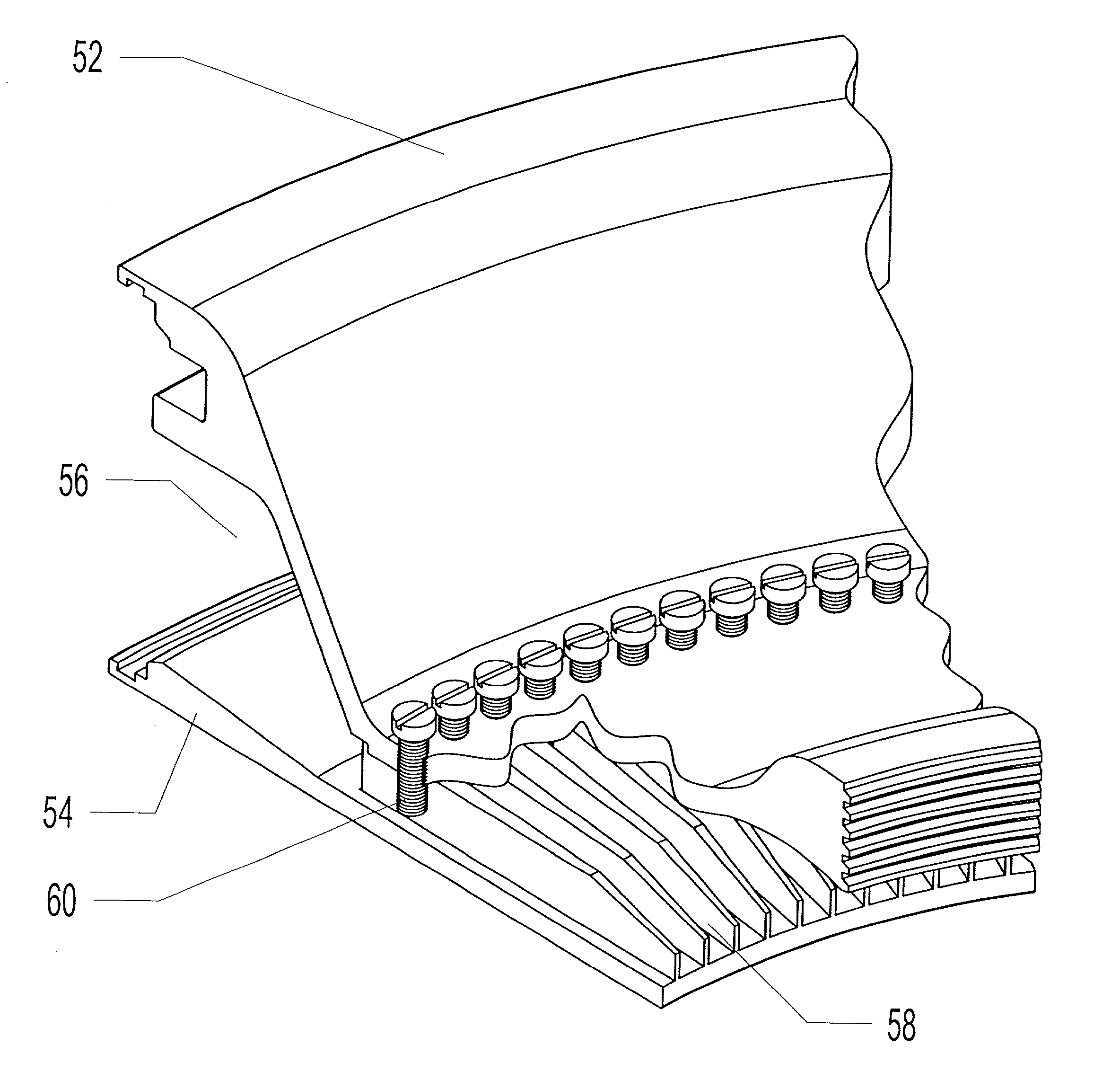
[0017] Manually controllable barriers can be used as actuators to provide a low cost alternative to automatic control. These barriers can be provided as screws that are handled in a similar fashion to die adjustment bolts commonly used by operators when adjusting die lips for thickness optimization, or as blocks to block portions of an annular region between air inlet and lips. The thickness adjustment can be well pronounced and fine-tunable using procedures that are generally understood by operating personnel in other contexts. A further advantage is that the resolution attainable is high because there can be over 120 control zones even on very small processes and hoop stresses are not an issue.

Problems solved by technology

Additionally, variability of the cooling air and non-uniformity of air aspirated into the cooling air stream from the atmosphere surrounding the extrusion line are major contributors to film thickness variation.
The presence of such thickness variations creates problems that limit the throughput of downstream conversion equipment, such as printing presses, laminators, or bag machines.
In processes where the film is not converted in-line, but is wound onto a roll prior to converting, the thicker and thinner areas of many layers on the roll create hills and valleys on the roll surface, thus deforming the film and magnifying the subsequent converting problem.
The main problem with this approach is that the ambient conditions surrounding the process constantly change and require continuous monitoring and barrier and / or fan repositioning.
This approach also does not take care of the relatively narrow thickness bands associated with the die ports and spirals, but does allow the processor to use the highest performance equipment available on the market to maximize throughtput on the line.
A problem associated with all automatic systems is the necessary complexity which creates high cost and requires the use of skilled operators and maintenance personnel.
In these systems, localized, circumferentially variable, mechanical adjustments to the die lip cause detrimentally large hoop stress and elastic forces to develop in the die lip, thereby resisting deformation and spreading the effect of the adjustment over a larger area than that intended.
These problems limit the effective resolution.
These systems have correspondingly poor control over thickness variation but do not preclude the use of high performance cooling systems which maximize throughput rate.
Also, heat that is added to the die lip transfers this heat to the molten polymer, thereby raising its local temperature.
Due to the large volumes of air and associated turbulence involved, mixing occurs and significantly degrades the performance of this type of system.
Also, heat that is added to the cooling air have the drawback of losing cooling capacity since overall temperature is raised, thus forcing the throughput rate of film production to be lowered.
Typically, single flow designs of air rings that use this approach produce acceptable thickness control capability, but have a drawback in that the reduced cooling capability lowers processing throughput rate.
This approach has a significant limitation in that there is limited control range capability and can only partially compensate for variations present on a typical blown film process.
These systems suffer from the additional disadvantage of added complexity which adds significantly to cost and reduced resolution due to the size of the air blade actuators which limits the ability to control narrow thickness variations commonly present.
One drawback, however, is that the system cannot be fitted to smaller die diameters, i.e., less than about 10 inches (250 mm), due to space constraints.
Additionally, not all processors of film want to employ IBC systems within their process.

Method used


Image

  • External thickness control and method
  • External thickness control and method
  • External thickness control and method

Examples


Embodiment Construction

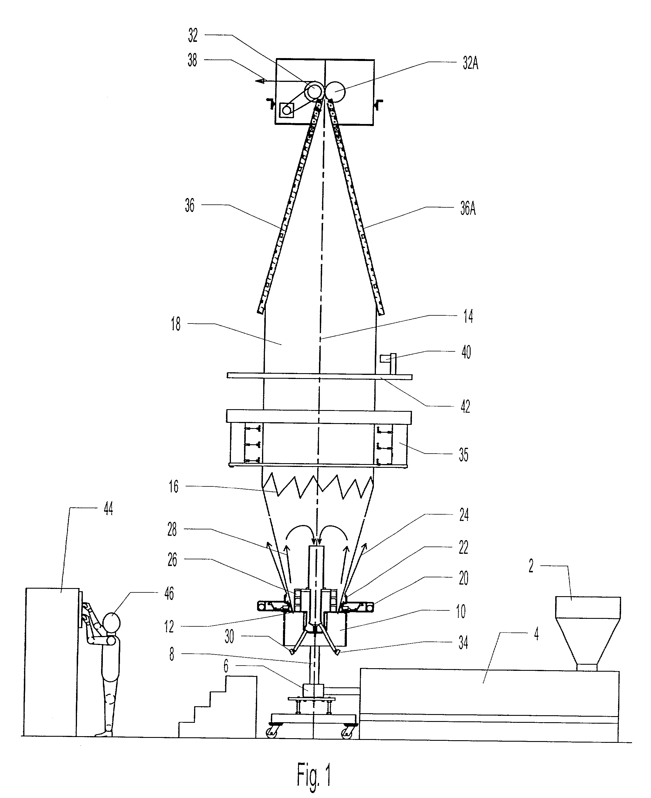
[0029] FIG. 1 illustrates a known system for extrusion of molten plastic resin to form blown film. Plastic pellets are fed into a feed hopper 2 and transferred into an extruder 4 where the pellets are melted, mixed, and pressurized by the action of an extruder screw. The melt exits extruder 4 and is conveyed through a die block 6 where it is directed upwardly through a vertical neck 8 into the bottom of a blown film die 10. The plastic melt flow is designed to form an annular, cylindrical plastic melt flow 12 which is extruded from an annular orifice at the top of die 10. This annular melt flow is continually drawn away from die 10 in a manner generally concentric with a process centerline 14. The annular diameter of the cylindrical plastic melt flow 12 enlarges as it progresses from the die until it reaches a frost line 16 (indicated diagrammatically by a saw-tooth line) to form a cooled, solidified plastic tubular film bubble 18.

[0030] Primary cooling air for the process is suppli...


PUM

PropertyMeasurementUnit
Fractionaaaaaaaaaa
Fractionaaaaaaaaaa
Thicknessaaaaaaaaaa

Abstract

A plastic resin extrusion line for the production of blown film includes an external thickness control device that provides a controllable amount of air from an inlet side through an annular region to one or two sets of lips. Barriers that can be manually or automatically controlled are provided in the annular region for localized control of air flow and thus for localized thickness control. The pressure drop across the barriers is significant relative to that in the lips.

Description

BACKGROUND OF THE INVENTION[0001] The present invention relates to improving the quality of products produced by plastic resin extrusion lines and to the production of blown film.[0002] When blown film is extruded, it typically is in the form of a continuous, vertically oriented tube. The tube, which is in a molten state as it exits a die, expands in diameter as it is pulled continuously upward. The diameter stabilizes to a more or less constant value when the tube cools sufficiently to solidify. This solidification occurs a short distance from the die at what is called the frost line. Air cooling systems such as air rings outside of the tube and internal bubble cooling (IBC) systems within the tube are provided close to the exit of the die to ensure that the tube cools quickly enough to remain stable.[0003] After solidifying, the tube passes through stabilizers of various designs and into a flattening device, known as a collapsing frame, to convert the inflated tube into a flattene...

Claims


Application Information

Patent Timeline
IPC IPC(8): B29C48/10B29C48/92
CPCB29C48/92B29C48/10B29C48/9125B29C48/913B29C2948/92152B29C2948/92923B29C2948/92428B29C2948/926B29C2948/92647B29C2948/92809B29C2948/92904B29C2948/92314
Inventor RANDOLPH, WILLIAMCREE, ROBERT E.
Owner ADDEX DESIGN
Learn More