Method and device for manufacturing pellets of hot-melt ink

a technology of hot-melt ink and pellets, which is applied in the directions of cocoa, dough shaping, printing, etc., can solve the problems of increasing the tendency of pellets to adhere to the walls of mold cavities, reducing the temperature of ink reservoirs, and reducing the production efficiency of hot-melt ink

Inactive Publication Date: 2002-09-19
OCE TECH
View PDF3 Cites 3 Cited by
  • Summary
  • Abstract
  • Description
  • Claims
  • Application Information

AI Technical Summary

Benefits of technology

0007] It is an object of the present invention to provide a method for manufacturing pellets of hot-melt ink, in which the pellets can be reliably and reproducibly withdrawn from the mold cavity.

Problems solved by technology

However, since the ink is consumed in the course of the printing process, and the ink reservoir accommodating the liquid ink within the printhead is preferably of a limited size, it is necessary to supply and melt solid ink while the printer is operating.
The latent heat required for melting the ink tends to decrease the temperature in the ink reservoir.
On the other hand, since the hot-melt ink has a relatively high melting point, it tends to solidify immediately when it comes into contact with the walls of the mold cavity.
This effect and the fact that the surface of the ink pellet is somewhat tacky, even when the temperature has dropped below the melting point, increases the tendency of the pellet to adhere to the walls of the mold cavity.
This makes it more difficult to reliably and reproducingly remove the molded pellet from the mold die.
Especially when the upper and lower dies of the mold are symmetrical, as must be the case for example when the pellet has a spherical shape, it is not predictable whether the pellet will adhere to the upper die or to the lower die when the dies of the molds are separated.
This tends to reduce the productivity of the molding process and / or necessitates the use of complex mechanisms for ejecting the molded product from the die.
In this case, however, a portion of the separating agent will inevitably be dispersed or diluted in the molten material, and this is not acceptable in the case of hot-melt ink because it deteriorates the quality of the ink.
For example, even minute particles of the separating agent, when dispersed in the ink, tends to clog the extremely fine nozzles of the printhead or change the ink properties such as its surface tension or crystallization point.

Method used


Image

  • Method and device for manufacturing pellets of hot-melt ink
  • Method and device for manufacturing pellets of hot-melt ink
  • Method and device for manufacturing pellets of hot-melt ink

Examples


Embodiment Construction

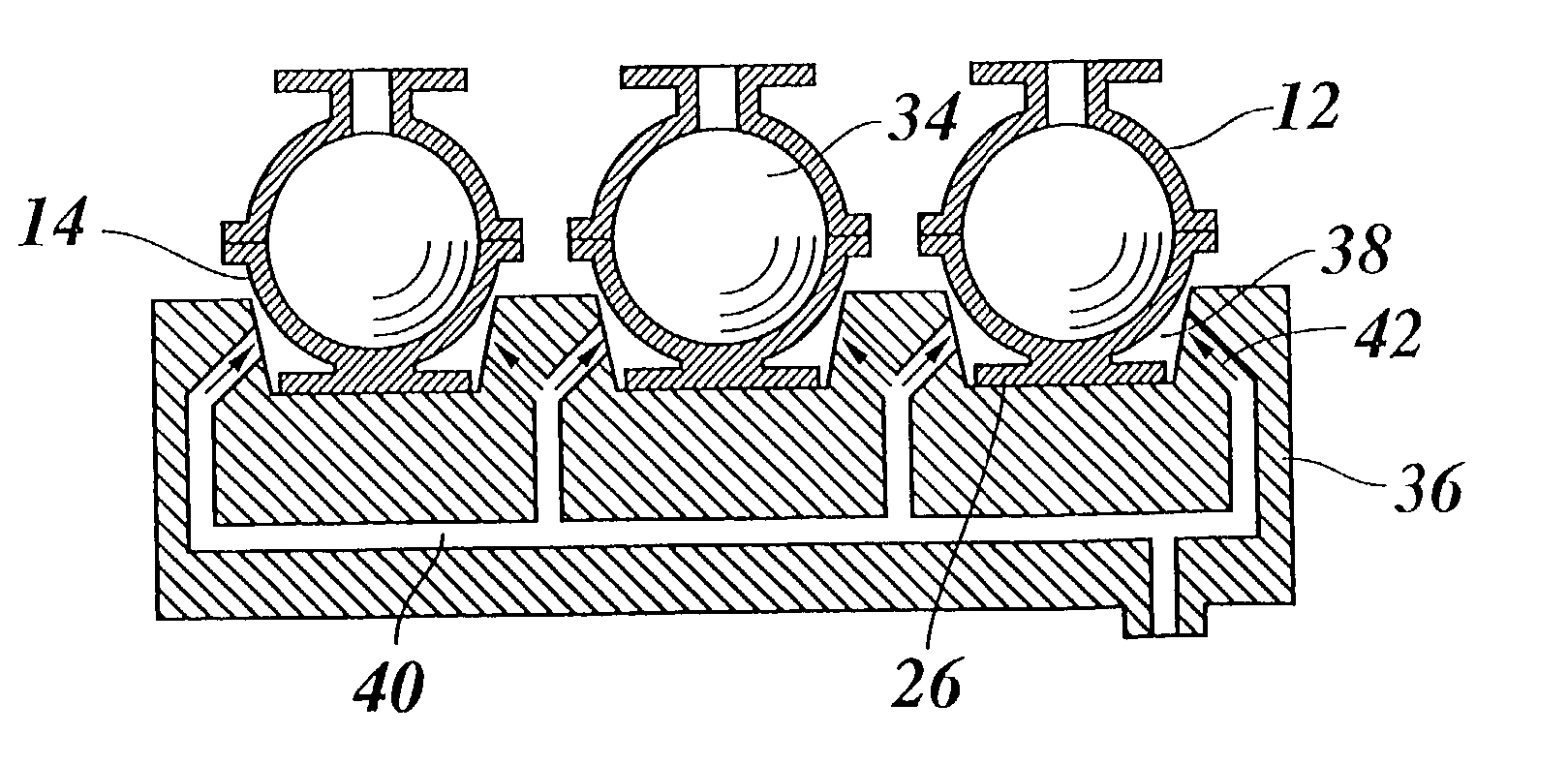
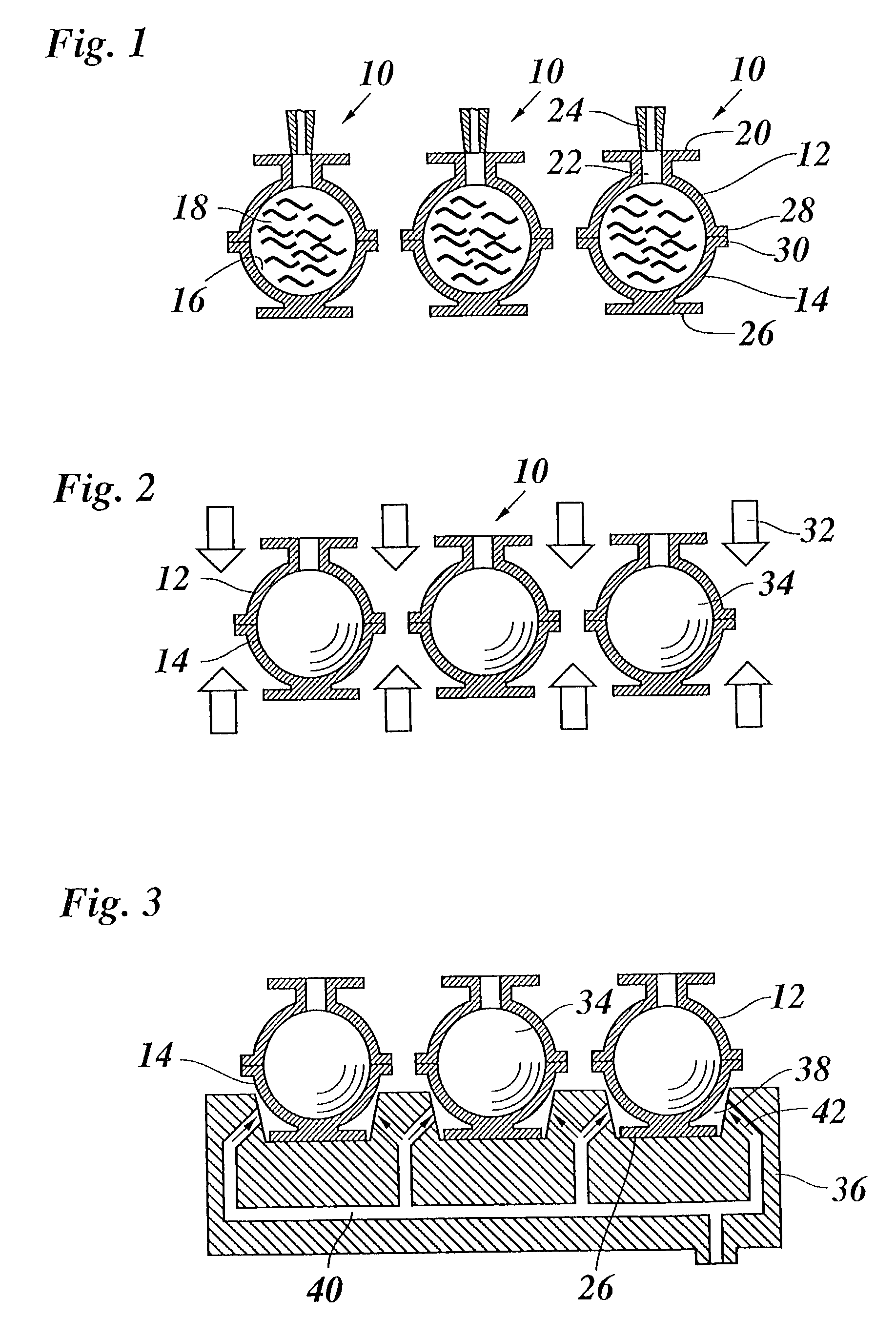
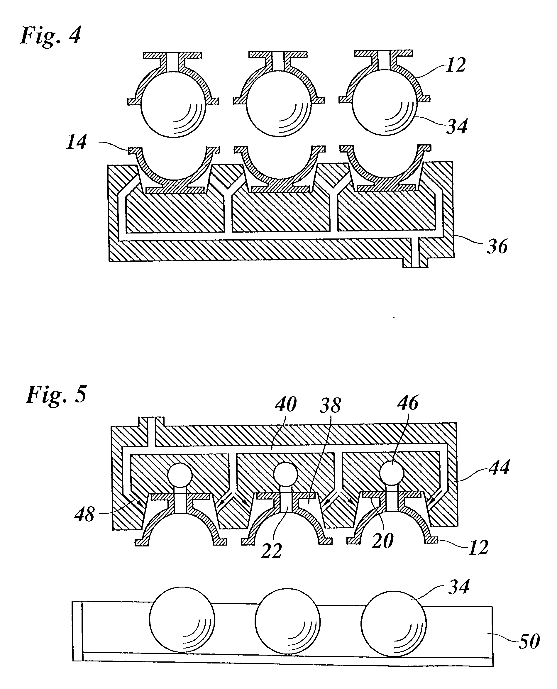
[0022] FIG. 1 shows a group of three molds 10, each of which comprises an upper die 12 and a lower die 14 each of which have a semi-spherical cup shape and, together, define a mold cavity 16 which is filled with molten hot-melt ink 18. The upper die 12 is integrally formed with a top flange 20 and has a runner hole 22 formed in the center of the flange 20, so that molten ink can be poured into the mold cavity 18 through a nozzle 24.

[0023] The lower die 14 is essentially mirror-symmetric relative to the upper die 12 and is supported on a bottom 26 formed integrally therewith. The lower edge of the upper die 12 and the upper edge of the lower die 14 are surrounded by circumferential flanges 28, 30 which are held in firm engagement with one another in order to sealingly close the mold cavity 16.

[0024] When the ink 18 has been poured in, as is shown in FIG. 1, the molds are transferred to a cooling stage illustrated in FIG. 2, where cold air 32 is blown against the outer surfaces of the...


PUM

PropertyMeasurementUnit
thicknessaaaaaaaaaa
temperatureaaaaaaaaaa
thicknessaaaaaaaaaa

Abstract

A method for manufacturing pellets of hot-melt ink which includes the steps of filling molten ink into a mold cavity defined by a first die and a second die of a mold, allowing the ink to cool down and solidify in the mold cavity, and heating at least one of the first and second dies for re-melting the surface of the ink pellet to facilitate its removal from the mold cavity.

Description

BACKGROUND OF THE INVENTION[0001] 1. Field of the Invention[0002] The present invention relates to a method and a mold for manufacturing pellets of hot-melt ink.[0003] 2. Background Art[0004] Certain types of inkjet printers employ a so-called hot-melt ink i.e. a wax-like ink material that is solid at room temperature and has a melting point in the order of, for example, 80 to 150.degree. C. In the printhead of the printer, the ink is heated above its melting point, so that droplets of liquid ink can be expelled through the nozzles of the printhead. In order to obtain a high quality of the printed image, the viscosity and hence the temperature of the molten ink in the printhead should be maintained essentially constant. However, since the ink is consumed in the course of the printing process, and the ink reservoir accommodating the liquid ink within the printhead is preferably of a limited size, it is necessary to supply and melt solid ink while the printer is operating. The latent ...

Claims


Application Information

Patent Timeline
Patent Type & Authority Applications(United States)
IPC IPC(8): B41J2/01B29C33/44B29C33/46B29C35/02B29C37/00B41J2/175B41M5/00C09D11/00
CPCB29C33/44B29C33/46B29C35/0266B29C37/0003B41J2/17593
Inventor HOLLANDS, PETER JOSEPHSCHREURS, WILHELMUS ANTONIUS MARIAWILLEMS, GUIDO GERARDUSVAN GERVEN, ANTONIUS JOHANNES JOZEFRAMEKERS, REINIER JAN
Owner OCE TECH
Why Eureka
Try Eureka