
Water heater and water heater component construction

Inactive Publication Date: 2002-10-17
RHEEM AUSTRALIA PTY LIMITED
View PDF0 Cites 24 Cited by
  • Summary
  • Abstract
  • Description
  • Claims
  • Application Information

AI Technical Summary

Benefits of technology

[0055] In accordance with one aspect of the present invention there is provided an instantaneous gas fired water heater comprising a heat exchanger through which water flows to be heated by a gas fired burner, the heat exchanger having a cold water inlet and a hot water outlet, an air tight chamber positioned downstream of the hot water outlet of the heat exchanger whereby when the demand for hot water ceases, the internal pressure within the hot water system causes hot water to flow from the heat exchanger into the air chamber to reduce the temperature of the heat exchanger.

Problems solved by technology

This type of water heater is typically pressure dependent with limitations on the flow rate of hot water it can sustain.
However this solution has led to increased susceptibility to scaling and its difficulties in the prior art.
Also difficulties exist in constructing and assembling cost effective, long life heat exchangers for this type of water heater.
This type of water heater also generally has combustion chamber surrounds which have a relatively high heat loss to the surroundings.
The lack of cost effectiveness relating to construction and assembly result from the fact that prior art instantaneous water heater heat exchangers are manufactured from a fin and tube construction.
This is a costly and time consuming construction method.
Another problem of prior art instantaneous water heaters is that because of a single water path through the fin and tube construction such water heaters experience a significant pressure drop across the inlet and outlet to the heat exchanger.
The construction of prior art instantaneous water heater heat exchangers have been susceptible to scaling.
Hot spots in heat exchangers, particularly a problem in fin and tube constructions, can result in a higher incidence of scaling.
One of the particular difficulties with these systems is that there can be a significant thermal lag on the hot potable water circuit.
This thermal lag almost always results in large quantities of water being wasted until the hot potable water arrives at a user's water spout.

Method used


Image

  • Water heater and water heater component construction
  • Water heater and water heater component construction
  • Water heater and water heater component construction

Examples


Embodiment Construction

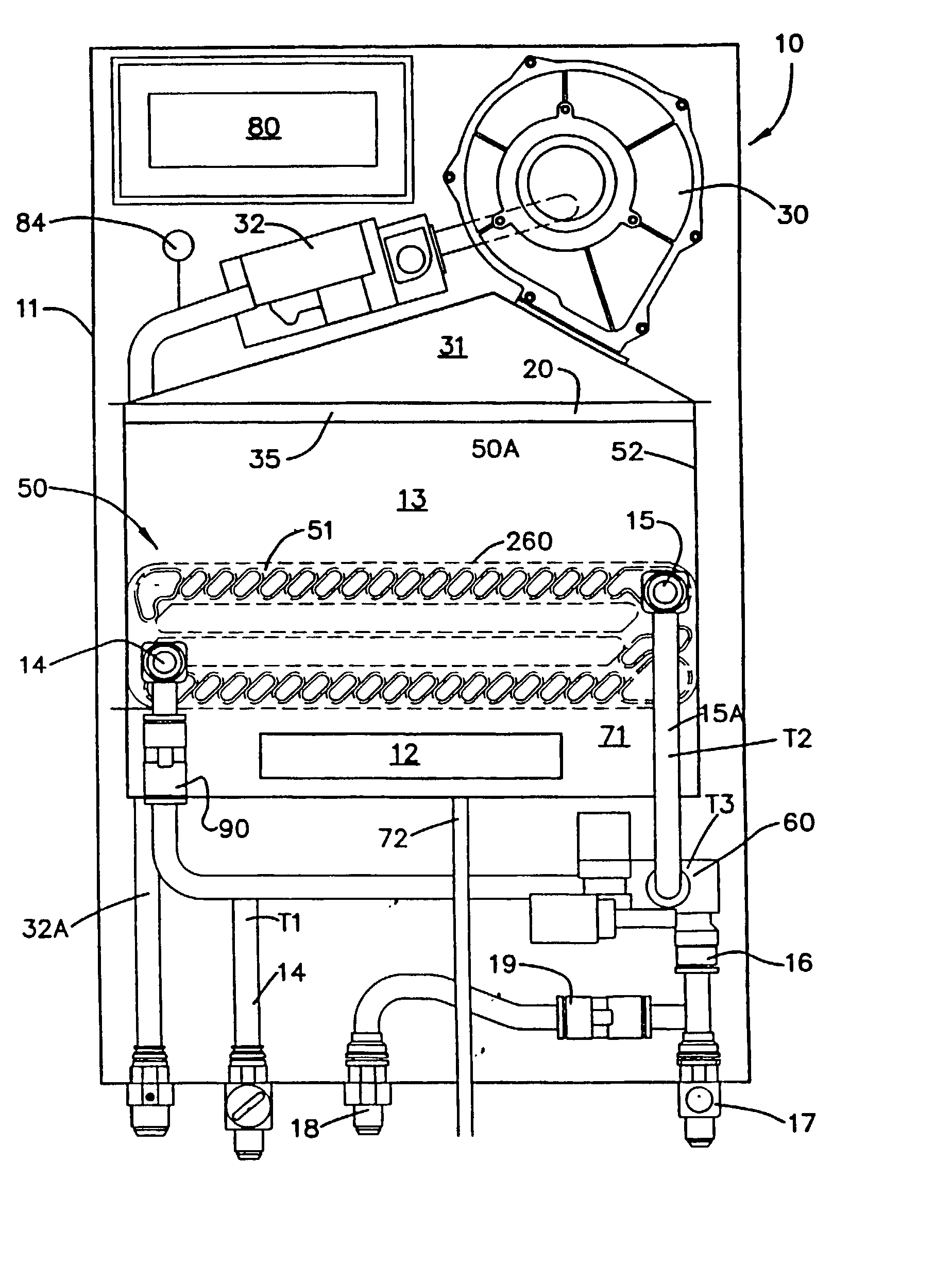
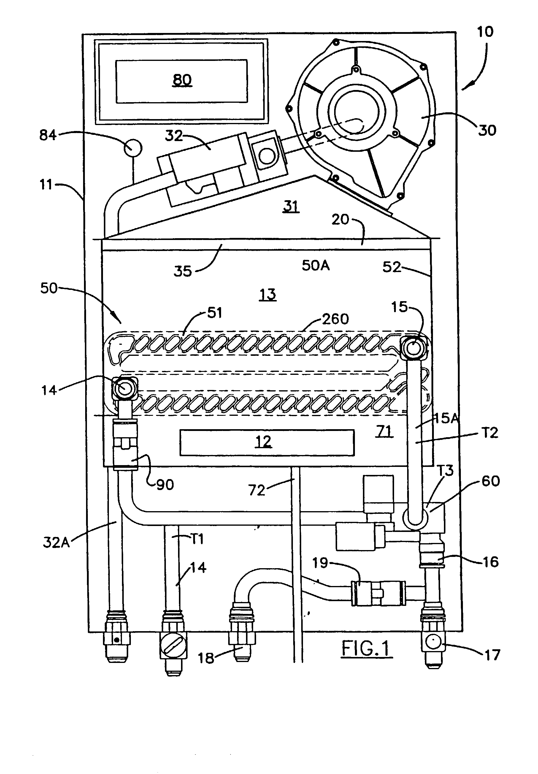
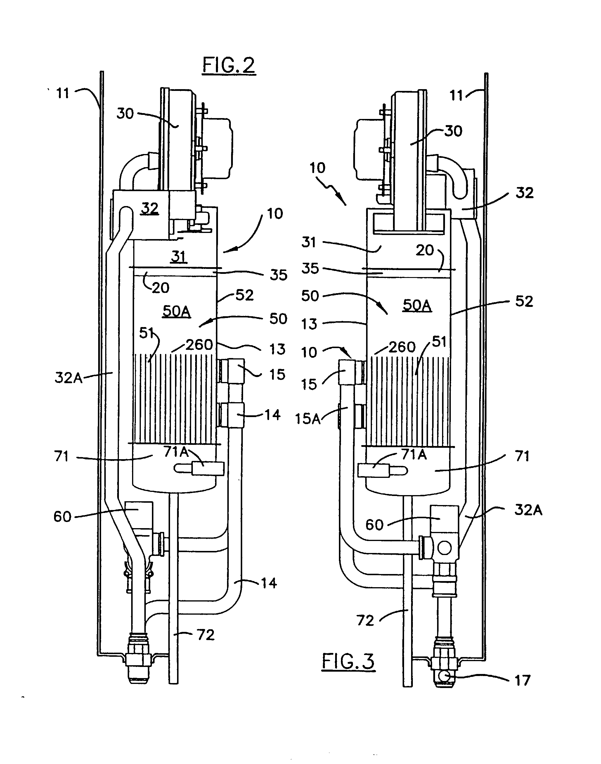
[0119] A domestic water heater 10 is illustrated in FIGS. 1 to 3, and is fuelled by gas and operates to provide an instantaneous flow of hot water.

[0120] As shown in FIGS. 1 to 3, the water heater 10 is housed in a rectangular enclosure 11 that is designed to be mounted flush against an external wall. The heater needs to be coupled to a supply of gas and it is understood that the heater can be adapted to work on a variety of commercially available gases. The combustion of the air gas mixture forms combustion products which are vented to the atmosphere via a small aperture 12 at the front 13 of the heater. Alternatively, the heater can be installed internally with exhaust gases being vented to the atmosphere via a small flue that would extend either through the wall cavity or up through the ceiling.

[0121] In summary, the water heater 10 has a burner 20 positioned above a water jacket assembly 50 so that heat and combustion products from the gas burner 20 pass through a heat exchanger...


PUM

PropertyMeasurementUnit
Angleaaaaaaaaaa
Lengthaaaaaaaaaa
Thicknessaaaaaaaaaa

Abstract

A water jacket assembly for an instantaneous gas fired water heater, the assembly including pressed profiled plates made of copper or copper coated steel, one plate being the inverted image of the other, said plates being placed together in pairs, the pairs of plates being arranged in a parallel array to form a heat exchanger, the heat exchanger being bordered by a water jacket comprising overlapping side and end panels of copper or copper coated steel attached to the array of plates, the assembly being fused together to define a combustion chamber with discrete combusted gases and water passages within said assembly.

Description

[0001] This patent application is a continuation application of PCT application serial number PCT / AU99 / 01106 filed on Dec. 14, 1999 (published in the English language on Jun. 21, 2001). This patent application is a continuation-in-part application of U.S. patent application Ser. No. 09 / 719,675 filed on Feb. 9, 2001, which was a 35 U.S.C. .sctn.371 of PCT application serial number PCT / AU99 / 00473 filed on Jun. 15, 1999 (published in the English language on Dec. 23, 1999), which claimed the benefit of Australian patent application number PP 4105 filed on Jun. 15, 1998. Each of these applications is hereby incorporated by reference.I. FIELD OF THE INVENTION[0002] This present invention relates to a fired instantaneous water heaters and other instantaneous types such as combination boilers, central room heaters, commercial and industrial water heaters and water processing systems to name some others. More particularly the present invention relates to a heat exchanger and a water jacket a...

Claims


Application Information

Patent Timeline
IPC IPC(8): B21D53/04B23P15/26F24H1/12F28D9/00F28F21/08
CPCB21D53/04B23P15/26F28F21/085F28D9/0043F28D9/0056F24H1/124F28F2250/102
Inventor MANLEY, DAVID WILLIAMMASTALERZ, KRZYSZTOFCAMP, MARTIN HENRYADAM, QUENTIN ARTHUR CARL
Owner RHEEM AUSTRALIA PTY LIMITED
Features
  • Generate Ideas
  • Intellectual Property
  • Life Sciences
  • Materials
  • Tech Scout
  • Unparalleled Data Quality
  • Higher Quality Content
  • 60% Fewer Hallucinations
Learn More