Solid state electrochromic device, and mirror system and crt display using same

a technology of electrochromic devices and mirrors, applied in the field of solid-state electrochromic devices, can solve the problems of disadvantageous limitation of the width of the opposed glass, disadvantageous loss of operability upon attachment, so as to improve operability upon attachment and facilitate the attachment of terminals

Inactive Publication Date: 2002-10-17
MURAKAMI CORP
View PDF1 Cites 86 Cited by
  • Summary
  • Abstract
  • Description
  • Claims
  • Application Information

AI Technical Summary

Benefits of technology

0012] In order to achieve the above objects, a solid-state EC device according to the present invention comprises a lower transparent conductive layer formed into filmy shape on a glass substrate, partially provided with a groove, and insulated with the groove, an electrochromic layer layered on the lower transparent conductive layer, an upper transparent conductive layer formed into filmy shape over a portion insulated with the groove of the lower transparent conductive layer, and a top of the electrochromic layer, and ...

Problems solved by technology

However, difficulty in working metal materials into the metal clip 37 having several tens of micrometers or so that is as small as the thickness of a resin of the solid-state EC device 30 would disadvantageously impose limitations on the width of the opposed glass plate 36 not wider than the width of the glass substrate 31.
In addition, insufficient introduction of stress due to a reduced metal thickness would make it difficult for the metal clip 37 to exert a holding power thereof derived from a stress introduced within a resiliency range, disadvantageously impairing operability upon attachment.
These disadvantages would result from application of the solid-state EC device 30 to a mirror, as well.
On the other hand, as is...

Method used


Image

  • Solid state electrochromic device, and mirror system and crt display using same
  • Solid state electrochromic device, and mirror system and crt display using same
  • Solid state electrochromic device, and mirror system and crt display using same

Examples


Embodiment Construction

[0025] A description will now be given of preferred embodiments of the present invention with reference to the accompanying drawing.

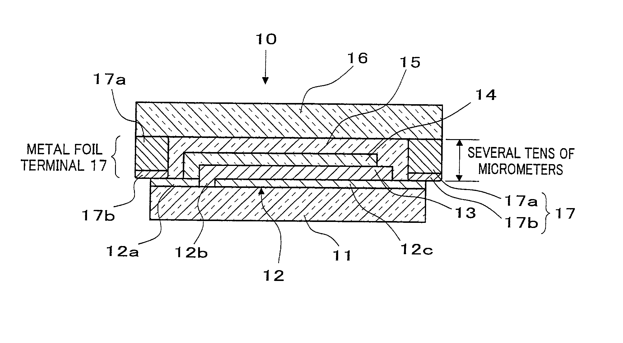
[0026] Referring first to FIG. 1, a description will be given of a solid-state EC device according to an embodiment of the present invention. FIG. 1 is a sectional view of the solid-state EC device according to the embodiment of the present invention.

[0027] As shown in FIG. 1, a solid-state EC device 10 is provided with a lower transparent conductive coating 12 made of ITO or the like on a top face of a glass substrate 11, and a groove 12b is formed in part of the lower transparent conductive coating 12 so as to provide an insulated portion 12a. The lower transparent conductive coating 12 is comprised of two portions, that is: an insulated portion 12a insulated with the groove 12b, and a body portion 12c, in order to obtain terminals for two electrodes from these portions. The width dimension of the lower transparent conductive coating 12 including the ...


PUM


Abstract

There is provided a solid-state electrochromic device including a lower transparent conductive layer (12) formed into filmy shape on a glass substrate, partially provided with a groove (12b), and insulated with the groove (12b), an electrochromic layer (13) layered on the lower transparent conductive layer (12), and an upper transparent conductive layer (14) in direct contact with an insulated portion (12a) of the lower transparent conductive layer. Metal foil terminals (17) made of a metal foil (17a) to which an electrically conductive adhesive material (17b) is applied are bonded to an end of a body portion (12c) of the lower transparent conductive layer and an end of the insulated portion (12a) of the insulated lower transparent conductive layer.

Description

[0001] This invention relates to a solid-state electrochromic device using a metal foil terminal as a lead-in terminal for electrodes of the device, and a mirror system and CRT (or Cathode Ray Tube) display using the device.[0002] Reversible transitions between colored and colorless states upon oxidation or reduction caused reversibly by application of voltage are called the phenomenon of electrochromism. Electrochromic (hereinafter referred to as EC) devices that use materials presenting such electrochromic features and are designed to change the color states by manipulating voltages are utilized for display devices, light quantity control devices, and the like across various industrial fields.[0003] An example of conventional solid-state EC devices is illustrated in FIG. 6. In a solid-state EC device 30, a lower transparent conductive coating 32 made of indium tin oxide (ITO) or the like is provided on a glass substrate 31, and a groove 32b is formed to provide an insulated portio...

Claims


Application Information

Patent Timeline
IPC IPC(8): G02F1/153G02F1/155G02F1/161H04N5/65H04N5/72
CPCG02F1/153G02F1/155H04N5/72H04N5/65G02F1/161
Inventor MOCHIZUKA, TAKUOTERADA, YOSHIYUKI
Owner MURAKAMI CORP
Why Eureka
Try Eureka