Modular gas-pressured needle-less injector

a module, needleless technology, applied in the direction of suction devices, intravenous devices, other medical devices, etc., can solve the problems of pain for patients, high production cost of traditional needle injectors, hypodermic syringes, etc., and achieve the effect of reducing the kickback

Inactive Publication Date: 2002-10-17
PENJET CORP
View PDF0 Cites 12 Cited by
  • Summary
  • Abstract
  • Description
  • Claims
  • Application Information

AI Technical Summary

Benefits of technology

[0013] In another embodiment of the instant invention, the needle-less injector includes a mechanism for mitigating the kickback associated with releasing compressed gas from the engine. Grips may be included on the engine, mechanically coupling the engine to an element of the needle-less injector that is affixed to the housing, thereby preventing the engine from separating from the housing upon release of compressed gas from the engine. Also, retainer hooks on the interior of the trigger corresponding to latch retainer mechanisms on the exterior of the housing further prevent the engine from separating from the housing.
[0071] During the administration of an injection with the needle-less injector, several mechanisms act to mitigate the kickback associated with releasing compressed gas from the engine housing. The grips on the valve body operatively couple with the locking ring on the exterior surface of the diffuser and the retainer hooks on the retainer hook mechanisms operatively lock at each successive saw tooth of the latch retainer mechanisms. Such safety features not only function to avoid potential injury, but further insure proper delivery of liquid through an injection surface.

Problems solved by technology

In addition, the traditional method of intradermal injections requires actual physical contact and penetration of a needle through the skin surface of the patient, which can be painful for the patient.
Traditional needle injectors, such as hypodermic syringes, are also expensive to produce and difficult to use with prepackaged medication doses.
Needle injectors also suffer from increased danger of contamination exposure to health care workers administering the injections, and to the general public when such injectors are not properly disposed of.
However, not only are conventional jet injectors cumbersome and awkward, but, existing conventional jet injectors are only capable of subcutaneous delivery of a medication beneath the skin layers of a patient.
Conventional jet injectors are also somewhat dangerous to use, since they can be discharged without being placed against the skin surface.
In addition, jet injectors that have not been properly sterilized are notorious for creating infections at the injection site.
Moreover, if a jet injector is not positioned properly against the injection site, the injection can result in wetting on the skin surface.
Problems associated with improper dosage amounts may arise as well, if some portion of the fluid intended for injection remains on the skin surface following an injection, having not been properly injected into and / or through the skin surface.
It should be noted, however, that compression spring propelled jet injectors do not offer linear delivery speeds (constant speed of the fluid being injected).
In addition to this problem, spring propelled jet injectors with weak (e.g., deteriorated) springs often slow fluid delivery speed down while an injection is being administered, resulting in improper fluid penetration.
Reduced speed of the fluid can cause improper dosing and bruising at the injection site when the injection surface is the skin of a human recipient.
In a jet injector, if the inert gas is not quickly and properly expelled, fluid may be improperly injected, as with those devices employing a compression spring.
Difficulties arise in the need to maintain tight tolerances on the breakable member, since minor changes in thickness can dramatically effect the pressure needed to deploy the gas from the gas chamber of the device.
In addition, the broken shards of the breakable member are ejected at high speed when the gas is expelled and these shards can occasionally jam between the plunger driver and the housing, thereby preventing proper operation of the needle-less injector.
Attempts to prevent small shards from being formed would obviate some of this potential, but tend to make activation of the device more difficult.
Gas power sources for needle-less injectors that employ either pop valves or breakaway tab valves to release the inert gas stored in their respective gas chambers, however, may only be opened once, thereby presenting difficulty with regard to quality control testing measures.
Further, operation of many injectors requires a user to depress a trigger, relying mainly on resistance force from the injection surface to initiate an injection.
Where the underlying surface is sensitive, applying such pressure may not be advantageous.
Further, if the injection surface is slippery such a device may slide out of place during an injection rendering its use potentially injurious and possibly resulting in improper fluid delivery.

Method used


Image

  • Modular gas-pressured needle-less injector
  • Modular gas-pressured needle-less injector
  • Modular gas-pressured needle-less injector

Examples


Embodiment Construction

Operation of a Needle-less Injector

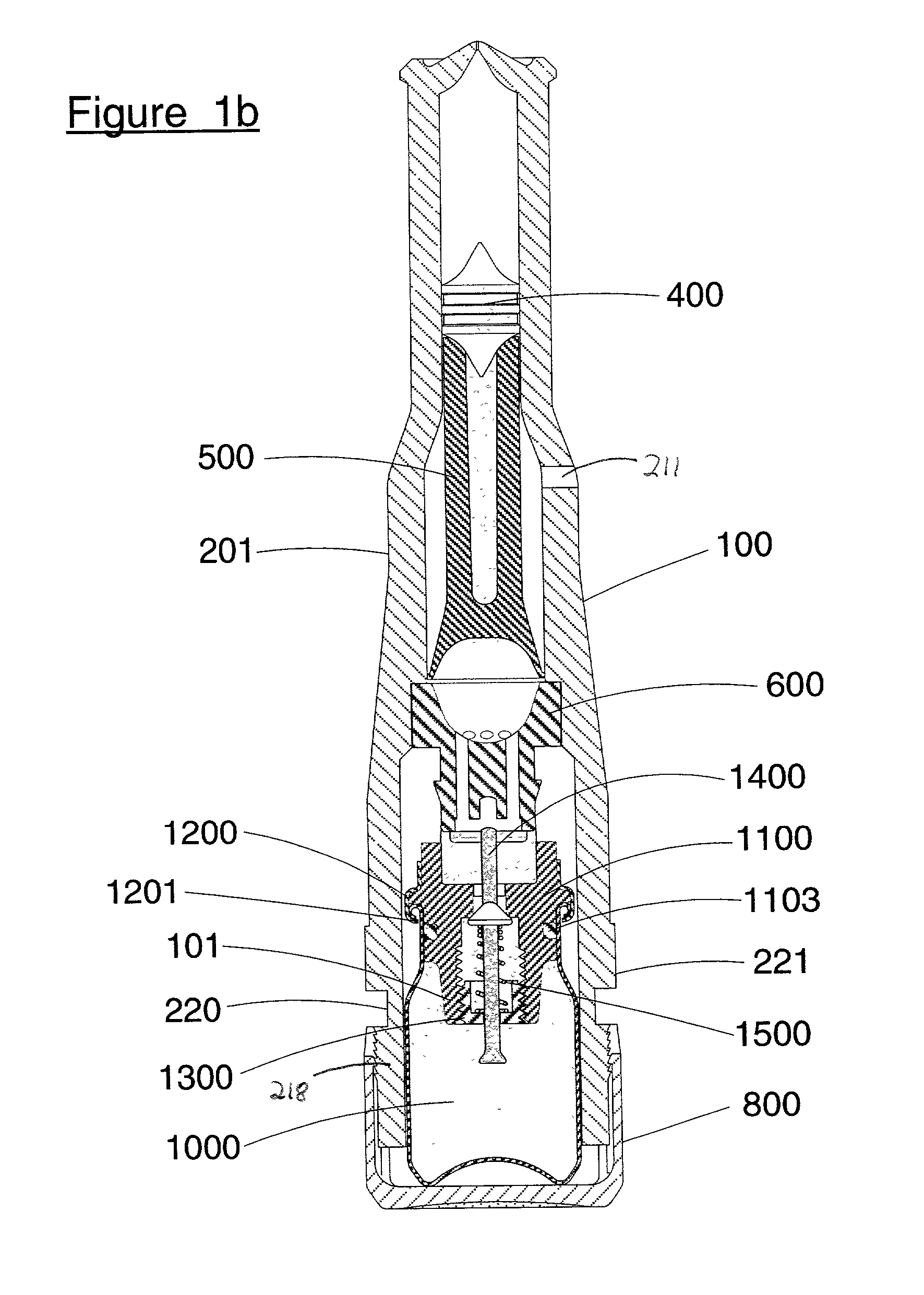
[0072] Prior to use, a needle-less injector is assembled in accordance with the instant invention, all elements thereof being gamma sterilized with the exception of the engine assembly. The engine assembly is checked for quality control purposes by opening and closing the valve, and thereafter the engine housing is filled with a suitable compressed gas. The interior portion of the housing between the proximate end of the housing and the proximate end of the plunger is then filled with 0.5 ml. of liquid. The needle-less injector is then assembled and stored for a prolonged period of time.

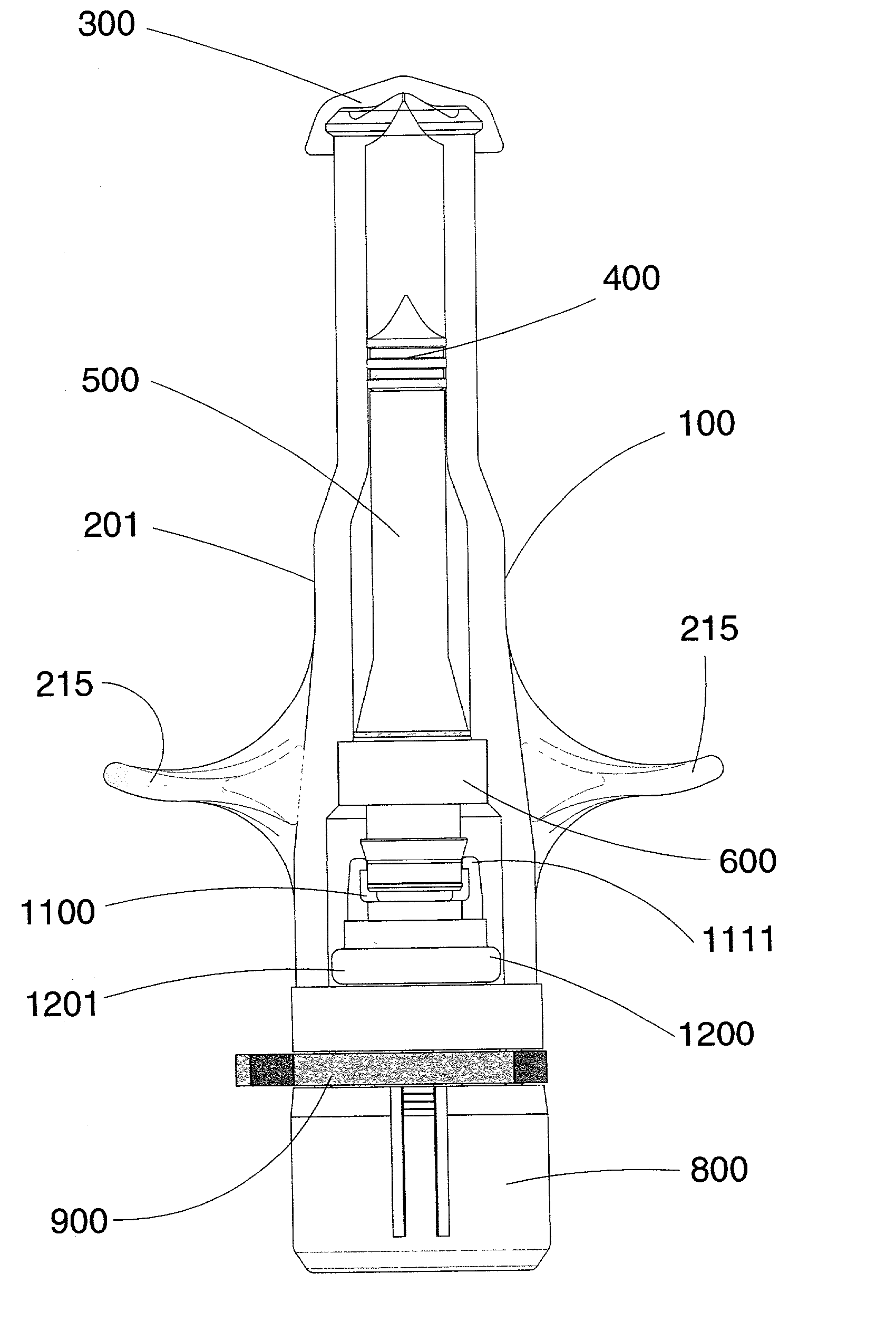
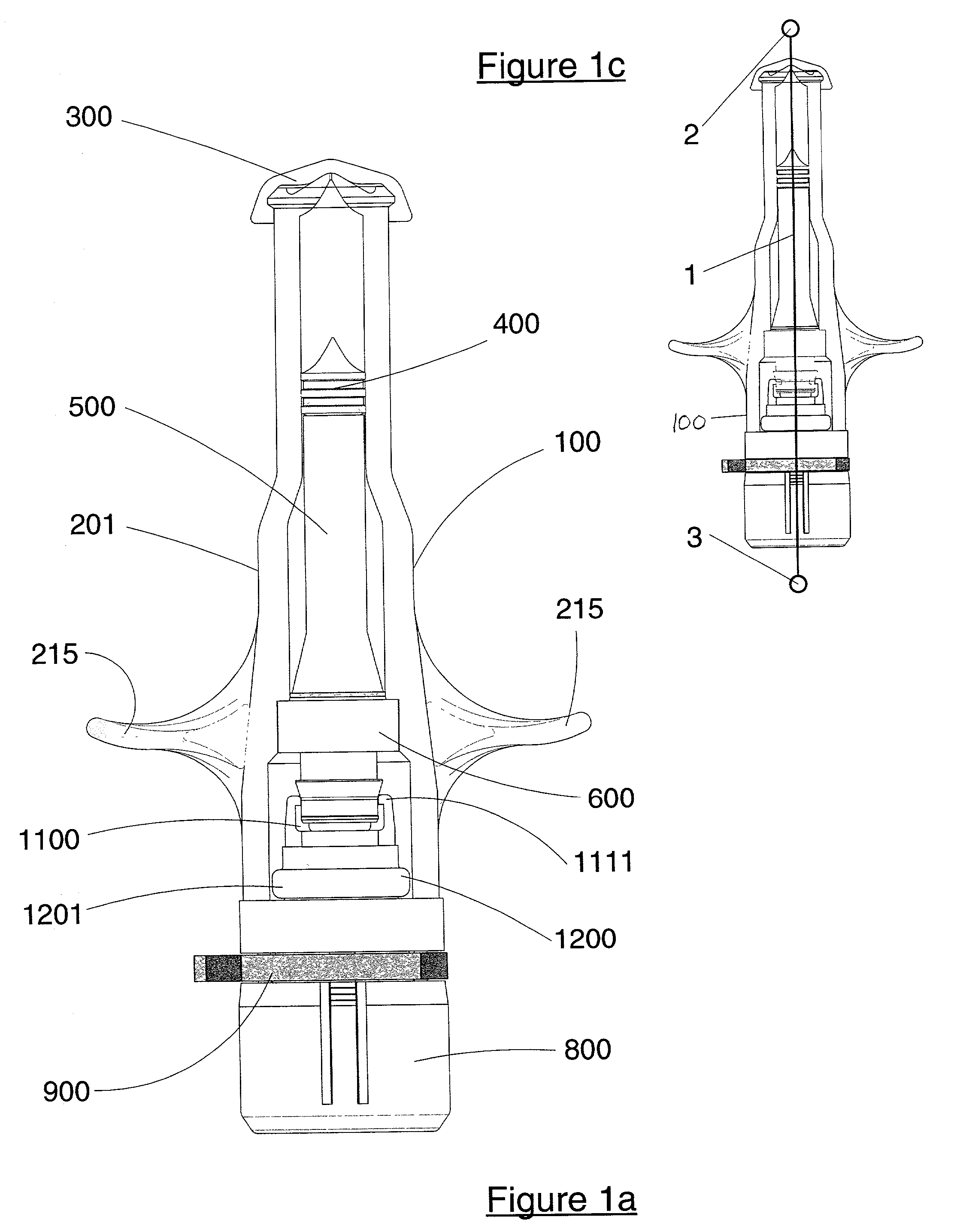
[0073] When ready for use (see FIG. 1a), the ampoule cap is removed from the proximate end of the housing by the user. Subsequently, the user also removes the safety clamp by bending and / or distorting the clamp. The user is performing self-administration of an injection and elects to employ the following configuration: the user's index and middle fingers are placed ...


PUM


Abstract

A needle-less injector suitable for injecting fluid through a surface includes a housing, a driver, an engine and a trigger. The housing contains a fluid and the engine contains a compressed gas. Upon application of sufficient force to the trigger, the compressed gas is released from the engine forcing the driver through the interior of the housing, expelling the liquid from the housing at a speed sufficient to pierce an injection surface. In one embodiment, the needle-less injector includes a mechanism for mitigating the kickback associated with releasing compressed gas from the engine. In another embodiment, the housing includes finger rests that provide stability and resistance to activate the device. In another embodiment, the engine is fitted with a reusable valve. In another embodiment, a safety clamp is included on the housing, preventing accidental activation of the device.

Description

[0001] This application is related to U.S. patent application Ser. No. 09 / 566,928, filed May 6, 2000. Further, this application generally relates to U.S. patent application Ser. No. 09 / 215,769, filed Dec. 19, 1998, now U.S. Pat. No. 6,063,053, which is a continuation of U.S. patent application Ser. No. 08 / 727,911, filed Oct. 9, 1996, now U.S. Pat. No. 5,851,198, which is a continuation-in-part of U.S. patent application Ser. No. 08 / 719,459, filed Sep. 25, 1996, now U.S. Pat. No. 5,730,723, which is a continuation-in-part of U.S. patent application Ser. No. 08 / 451,470, filed Oct. 10, 1995, now abandoned. This application is also generally related to U.S. patent application Ser. No. 09 / 192,079, filed Nov. 14, 1998, now U.S. Pat. No. 6,080,130, and to U.S. patent application Ser. No. [attorney docket No. 69816-0250782], filed Mar. 14, 2001.[0002] This invention relates to needle-less injectors, and in particular, modular gas-pressured needle-less injectors and methods of performing nee...

Claims


Application Information

Patent Timeline
Patent Type & Authority Applications(United States)
IPC IPC(8): A61M5/20A61M5/30
CPCA61M5/2053A61M2005/2073A61M5/30
Inventor CASTELLANO, THOMAS P.
Owner PENJET CORP
Why Eureka
Try Eureka