Dynamic frequency compensated operation amplifier

a technology of dynamic frequency compensation and operation amplifier, which is applied in the direction of amplifier modification, amplifier, gated amplifier, etc., to reduce detrimental interference, and achieve the effect of reducing power consumption and relatively large circuit siz

Inactive Publication Date: 2002-10-24
ANALOG DEVICES INC
View PDF0 Cites 18 Cited by
  • Summary
  • Abstract
  • Description
  • Claims
  • Application Information

AI Technical Summary

Problems solved by technology

Thus settling is an intrinsic problem in switched capacitor circuits.
But such circuits are relatively large in size and consume substantial power.

Method used


Image

  • Dynamic frequency compensated operation amplifier
  • Dynamic frequency compensated operation amplifier
  • Dynamic frequency compensated operation amplifier

Examples


Embodiment Construction

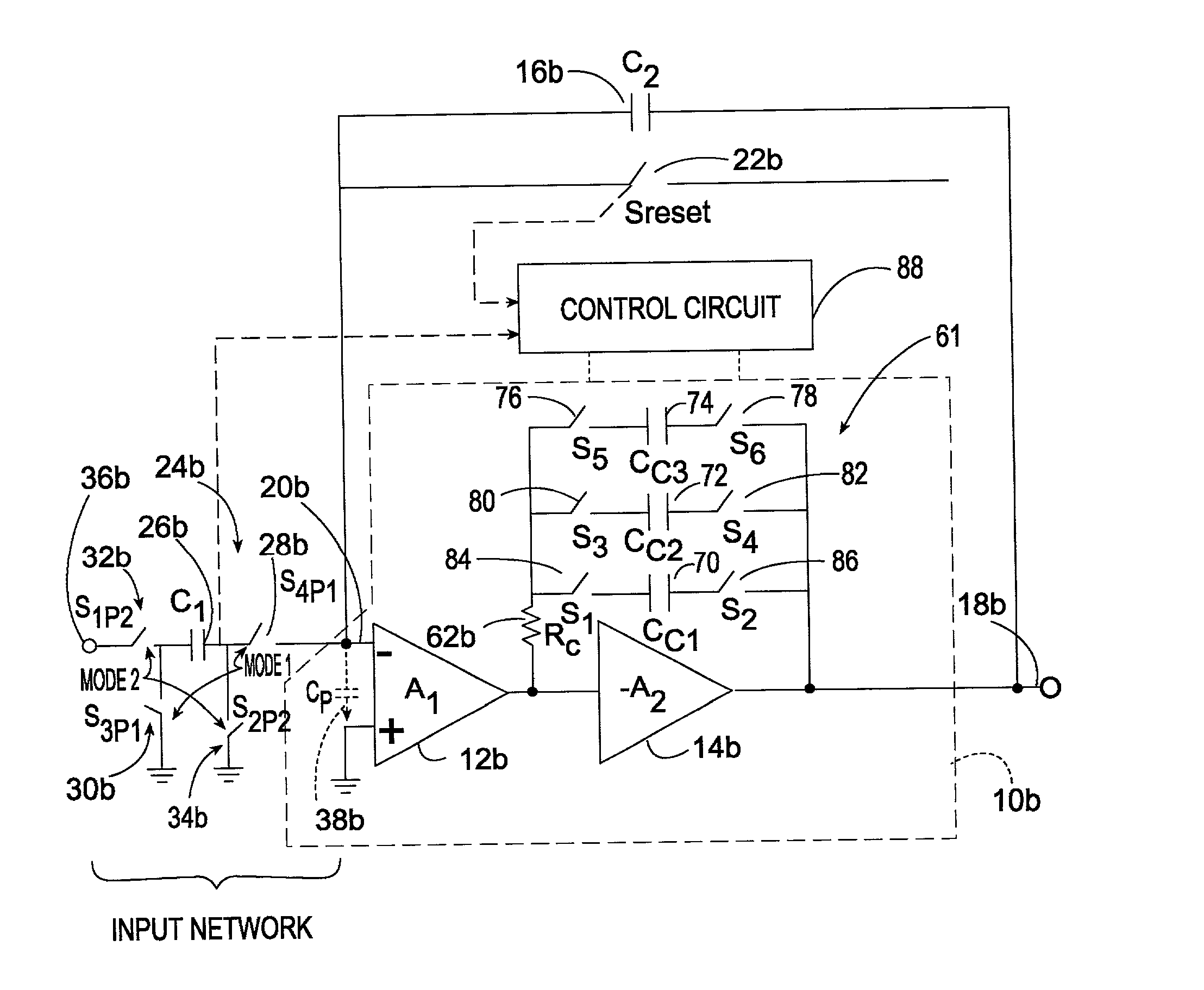
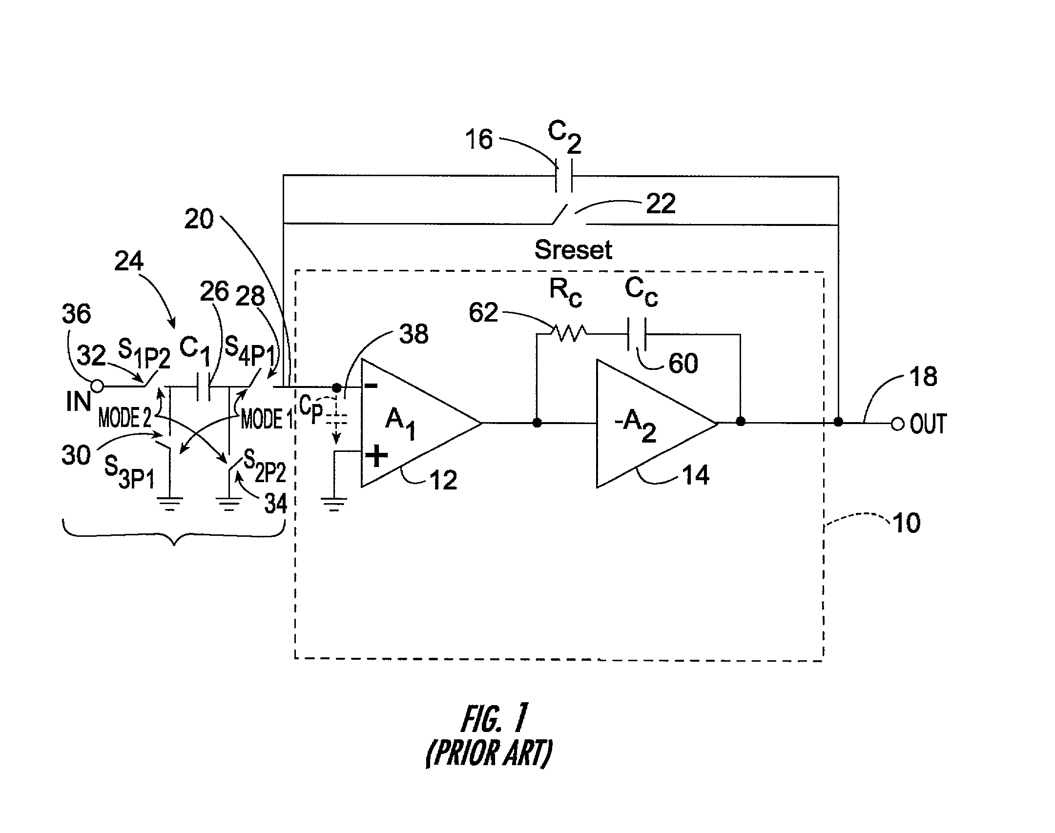
[0020] There is shown in FIG. 1, a prior art frequency compensated operational amplifier 10 which uses a pole splitting scheme to compensate for the frequency shift caused by the alternate connection and disconnection of the capacitor in the input network of the operational amplifier. Operational amplifier 10 includes a first differential to single ended amplifier stage 12 and a second stage 14. Feedback capacitor C.sub.2 16 is interconnected between the output 18 and input 20 of operational amplifier 10. Also connected between the output 18 and input 20 of operational amplifier 10 is reset switch 22 which when closed connects the output 18 to the input 20 of operational amplifier 10 thereby causing it to establish a unity gain condition. A switched capacitor input network 24 includes input capacitor C.sub.1 26 and four switches 28, 30, 32, and 34.

[0021] In operation in mode 2, switches 32 and 34 are closed and switches 28 and 30 are open so that the capacitor C.sub.1 is connected t...


PUM


Abstract

A dynamic frequency compensated operational amplifier having multiple gain settings includes a first differential to single ended amplifier stage; a second amplifier stage responsive to the first stage; a plurality of compensating capacitors; a multi-gain setting circuit for selectively setting the gain of the operational amplifier; and a control circuit, responsive to the gain set by the multi-gain setting circuit for connecting at least one of the compensating capacitors between the output and the input of the second amplifier stage for adjusting the frequency response of the operational amplifier.

Description

[0001] This invention relates to a dynamic frequency compensated operational amplifier having multiple gain settings.BACKGROUND OF INVENTION[0002] Switched capacitor circuits are widely used in implementing data convertors. There are typically two modes in a switched capacitor circuit, namely sampling and integrating modes. In the sampling mode, the input capacitor is connected between the input signal source and the ground. In the integrating mode, the input capacitor is connected between the inverting terminal of the operational amplifier and the ground. Thus the switching of the input capacitor in and out changes the gain of the operational amplifier. It is a characteristic of operational amplifiers that their phase shift varies with their gain and that phase shifts of more than -120.degree. begin to extend the settling time for a sample. As the phase shift grows toward -180.degree. the operational amplifier approaches positive feedback where settling never occurs. Thus settling ...

Claims


Application Information

Patent Timeline
Patent Type & Authority Applications(United States)
IPC IPC(8): H03F1/08H03F3/68H03F3/72
CPCH03F1/083H03F3/72H03F3/68
Inventor NGUYEN, KHIEM QUANG
Owner ANALOG DEVICES INC
Why Eureka
Try Eureka