System and method for improving image quality in processed images

a processing system and image technology, applied in image enhancement, image analysis, visual presentation, etc., can solve the problems of reducing the data volume by half or one-third, not working well for jpeg compression on non-realistic images, such as cartoons or line drawings, and not handling motion picture compression

Inactive Publication Date: 2002-11-07
HEWLETT PACKARD DEV CO LP
View PDF7 Cites 39 Cited by
  • Summary
  • Abstract
  • Description
  • Claims
  • Application Information

AI Technical Summary

Problems solved by technology

JPEG compression does not work very well on non-realistic images, such as cartoons or line drawings.
JPEG compression does not handle black-and-white (1-bit-per-pixel) images, nor does it handle motion picture compression.
The algorithm achieves much of its compression by exploiting known limitations of the human eye, notably the fact that small color variations are not perceived as well as small variations in brightness.
1. Transform the image into a suitable color space. This is a no-op for grayscale images. For color images, RGB information is transformed into a luminance / chrominance color space (e.g., YCbCr, YUV, etc). The luminance component is grayscale and the other two axes are color information.
2. (Optional) Down sample each component by averaging together groups of pixels. The luminance component is left at full resolution, while the chroma components are often reduced 2:1 horizontally and either 2:1 or 1:1 (no change) vertically. In JPEG, these alternatives are usually called 2h2v and 2h1v sampling, but you may also see the terms "411" and "422" sampling. This step immediately reduces the data volume by one-half or one-third. In numerical terms it is highly lossy, but for most images it has almost no impact on perceived quality, because of the eye's poorer resolution for chroma info. Note that down sampling is not applicable to grayscale data; this is one reason color images are more compressible than grayscale.
3. Group the pixel values for each component into 8.times.8 blocks. Transform each 8.times.8 block through a discrete cosine transform (DCT). The DCT is a relative of the Fourier transform and likewise gives a frequency map, with 8.times.8 components. Thus you now have numbers representing the average value in each block and successively higher-frequency changes within the block. The motivation for doing this is that you can now throw away high-frequency information without affecting low-frequency information. (The DCT transform itself is reversible except for round off error.)
4. In each block, divide each of the 64 frequency components by a separate "quantization coefficient" and round the results to integers. This is the fundamental information-losing step. The larger the quantization coefficients, the more data is discarded. Note that even the minimum possible quantization coefficient, 1, loses some info, because the exact DCT outputs are typically not integers. Higher frequencies are always quantized less accurately (given larger coefficients) than lower, since they are less visible to the eye. Also, the luminance data is typically quantized more accurately than the chroma data, by using separate 64-element quantization tables.
5. Encode the reduced coefficients using either Huffman or arithmetic coding.
6. Tack on appropriate headers, etc., and output the result. In normal "interchange" JPEG file, all of the compression parameters are included in the headers so that the decompressor can reverse the process. These parameters include the quantization tables and the Huffman coding tables.
This oversimplified case reveals two of the most difficult problems in motion compensation: 1) determining if an image is stationary; and 2) determining how and what portion of an image to extract for the portion of the image that moves.
However, when there is complex motion or new imagery, these error coding schemes may perform poorly, and the error signal may be harder to encode than the original signal.
For complex scenes and / or low bit rates, a number of visual artifacts may appear as a result of signal distortion from a compression system.
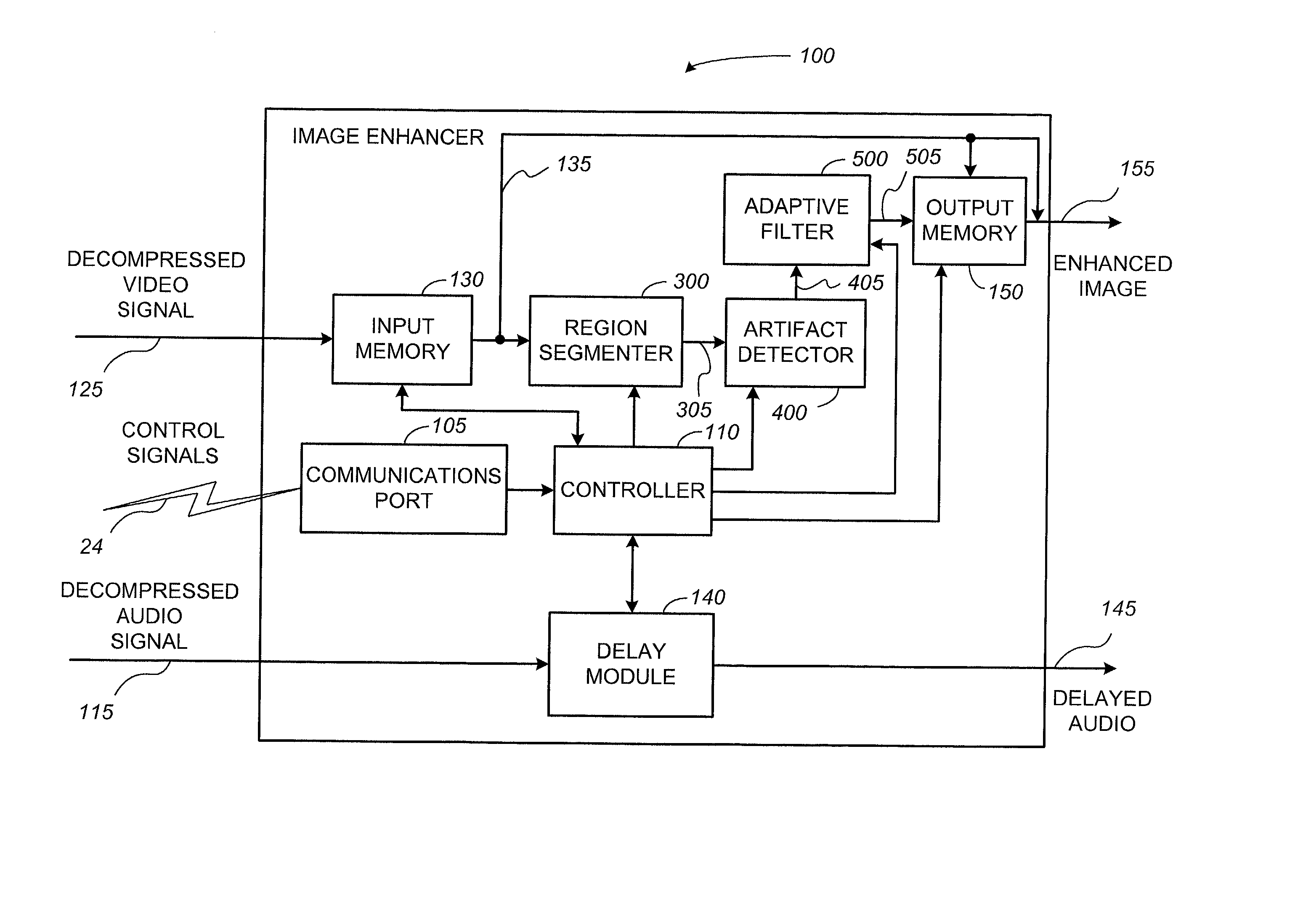
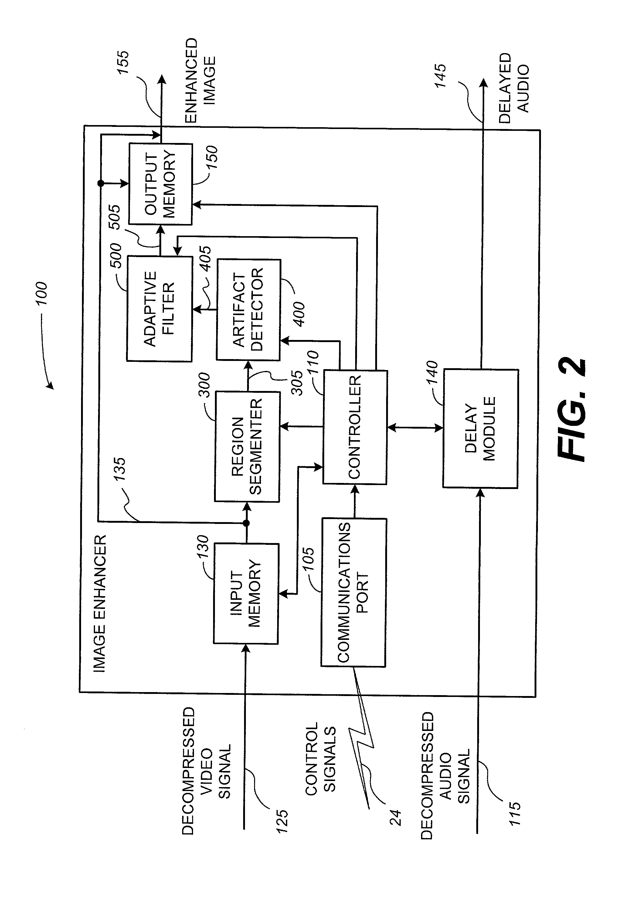
The primary visual artifacts affecting current image compression systems are blocking effects and intermittent distortions, often near object boundaries, often called mosquito noise.
Other artifacts include ripple, contouring, and loss of resolution.
Blocking effects are produced because adjacent blocks in an image are processed independently and the resulting independent distortion from block to block causes a lack of continuity between neighboring blocks.
In addition, block-type contouring, which is a special case of blocking effect, often results in instances when the intensity of an image is slowly changing.
Block DCT applications are not effective at representing sharp edges.
Accordingly, there is considerable distortion at sharp edges: the reconstructed edges are not as sharp as normal and the adjacent regions are not as uniform as they should be.
Mosquito noise is especially evident in images containing text or computer graphics.
Thus, most reproduced images may be adversely affected by blocking effects and edge distortion.
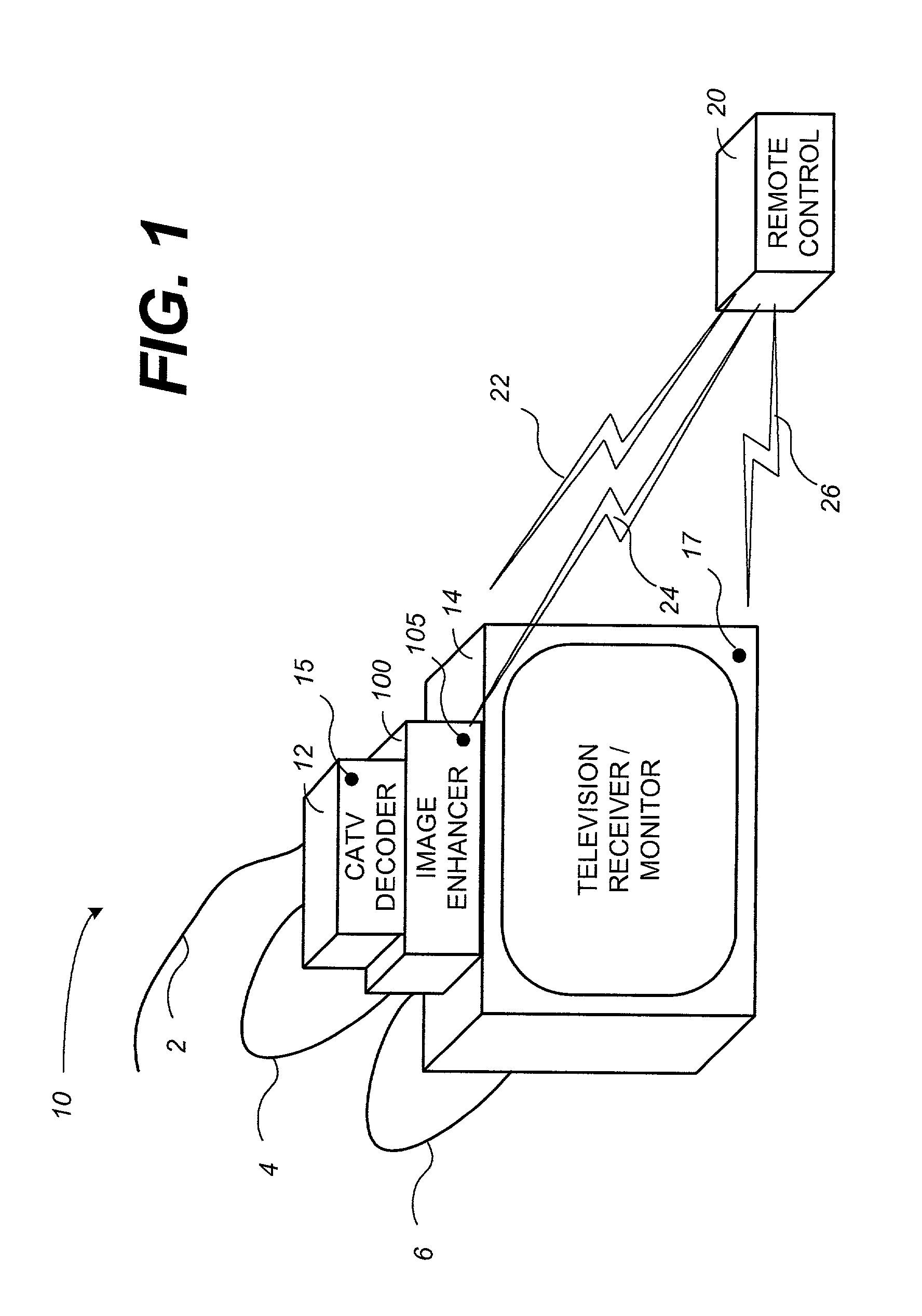
Whether the set-top box is functioning as a encoder or a decoder both analog TVs and DTVs are adversely affected by the block DCT coding introduced image artifacts.

Method used


Image

  • System and method for improving image quality in processed images
  • System and method for improving image quality in processed images
  • System and method for improving image quality in processed images

Examples


Embodiment Construction

[0038] Having summarized various aspects of the present invention, reference will now be made in detail to the description of the invention as illustrated in the drawings. While the invention will be described in connection with these drawings, there is no intent to limit it to the embodiment or embodiments disclosed therein. On the contrary, the intent is to cover all alternatives, modifications and equivalents included within the spirit and scope of the invention as defined by the appended claims.

[0039] Turning now to the drawings, wherein like referenced numerals designate corresponding parts throughout the drawings, reference is made to FIG. 1, which illustrates a schematic of an exemplary operational environment suited for an image enhancer. In this regard, an exemplary operational environment 10 may comprise a community antenna television (CATV) decoder 12, an image enhancer 100, a television receiver / monitor 14, and a multiple-unit remote control 20. As illustrated in FIG. 1,...


PUM


Abstract

A system and method for reducing image artifacts from a processed image are disclosed. An image enhancing system can be implemented with a memory device, an image region segmenter, an artifact detector, and a filter. The region segmenter may be configured to sub-divide an image frame. Each region may be processed by the artifact detector to identify when an image artifact is present in the region. The identified regions may be forwarded to the filter to smooth the harshness of the picture element discontinuities. The method for reducing image artifacts in a compressed and decompressed image can be broadly summarized by the following steps: receiving picture element data associated with at least one image frame; segmenting the at least one image frame into a plurality of regions in accordance with a first viewer selected imaging parameter; analyzing the plurality of segmented regions to identify regions that contain an image artifact in response to a second viewer selected imaging parameter; processing the identified regions with a filter such that at least one picture element data parameter is adjusted in response to both a third and a fourth viewer selected imaging parameters; and inserting adjusted picture element data values into the at least one image frame.

Description

[0001] 1. Field of the Invention[0002] The present disclosure relates to systems and methods for processing digital image signals. More particularly, the invention relates to a system and method that improves image quality by reducing the harshness of distortions in compressed digital image signals.[0003] 2. Discussion of the Related Art[0004] A digital image signal generally contains information associated with a plurality of picture elements, e.g., pixels, Digital images typically contain large amounts of information (e.g., color and brightness information related to each of the plurality of pixels) needed to reproduce the image. As a result, data compression is often implemented to reduce the amount of memory that images require for processing and storage. Data compression is important not just for long term digital storage of an image but for permitting reasonable data transfer rates over network connected devices.[0005] JPEG is a standardized image compression mechanism. JPEG s...

Claims


Application Information

Patent Timeline
Patent Type & Authority Applications(United States)
IPC IPC(8): G06T5/00G06T5/20
CPCG06T5/20G06T2207/20192G06T5/002
Inventor BAGGS, SCOTT
Owner HEWLETT PACKARD DEV CO LP
Why Eureka
Try Eureka