Continuous liquid infusion device

a liquid infusion device and liquid technology, applied in the direction of liquid/fluent solid measurement, volume metering, instruments, etc., can solve the problems of large weight, inconvenient patient transport, and device using electric syringe pump

Inactive Publication Date: 2002-11-07
ORCHIS
View PDF5 Cites 23 Cited by
  • Summary
  • Abstract
  • Description
  • Claims
  • Application Information

AI Technical Summary

Benefits of technology

[0019] As described above, the continuous liquid infusion device according to the present invention is structured to bias the liquid pushout plunger barrel via the locking member engaged with the piston and push out liquid in the liquid syringe by utilizing returning force of the piston due to negative pressure inside the vacuum pump barrel, which enables liquid infusion at constant infusion rate and amount over a long period of time and easy handling, and brings about an advantage in terms of cost.

Problems solved by technology

However, the infusion device using the electric syringe pump described above has a large weight and is inconvenient for the patient to carry when he / she moves as well as it is complicatedly structured and expensive.
Further, since the balloon infuser does not have constant contraction force of the balloon and liquid discharging force, it is difficult to continuously infuse liquid at a constant flow rate so liquid sometimes remains in the balloon.
Furthermore, with these conventional infusion devices driven by the balloon or the spring, it is difficult to maintain precision of the predetermined infusion rate and amount of liquid over a long time.
However, these conventional infusion devices utilizing negative pressure are not easy to handle because they need large force for operating the piston or the like to form negative pressure.
Moreover, since the infusion devices have the particular structure such as the center barrel provided in the second cylinder, they need to be handled with caution and their manufacturing cost is high.
Furthermore, it is difficult to maintain negative pressure, which is driving force for infusion, constant over a long time and there is a problem in precision of an infusion rate and amount of liquid.

Method used


Image

  • Continuous liquid infusion device
  • Continuous liquid infusion device
  • Continuous liquid infusion device

Examples


Embodiment Construction

[0050] A continuous liquid infusion device according to the present invention (hereinafter referred to as "infusion device of the present invention") will be explained based on the attached drawings.

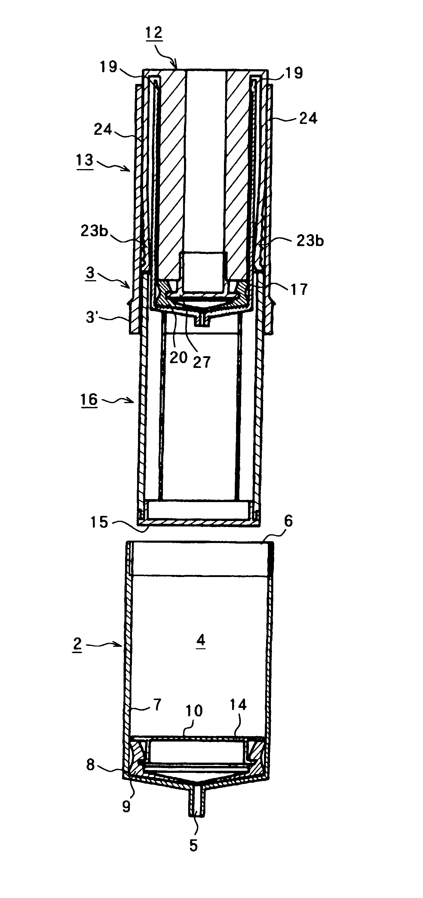
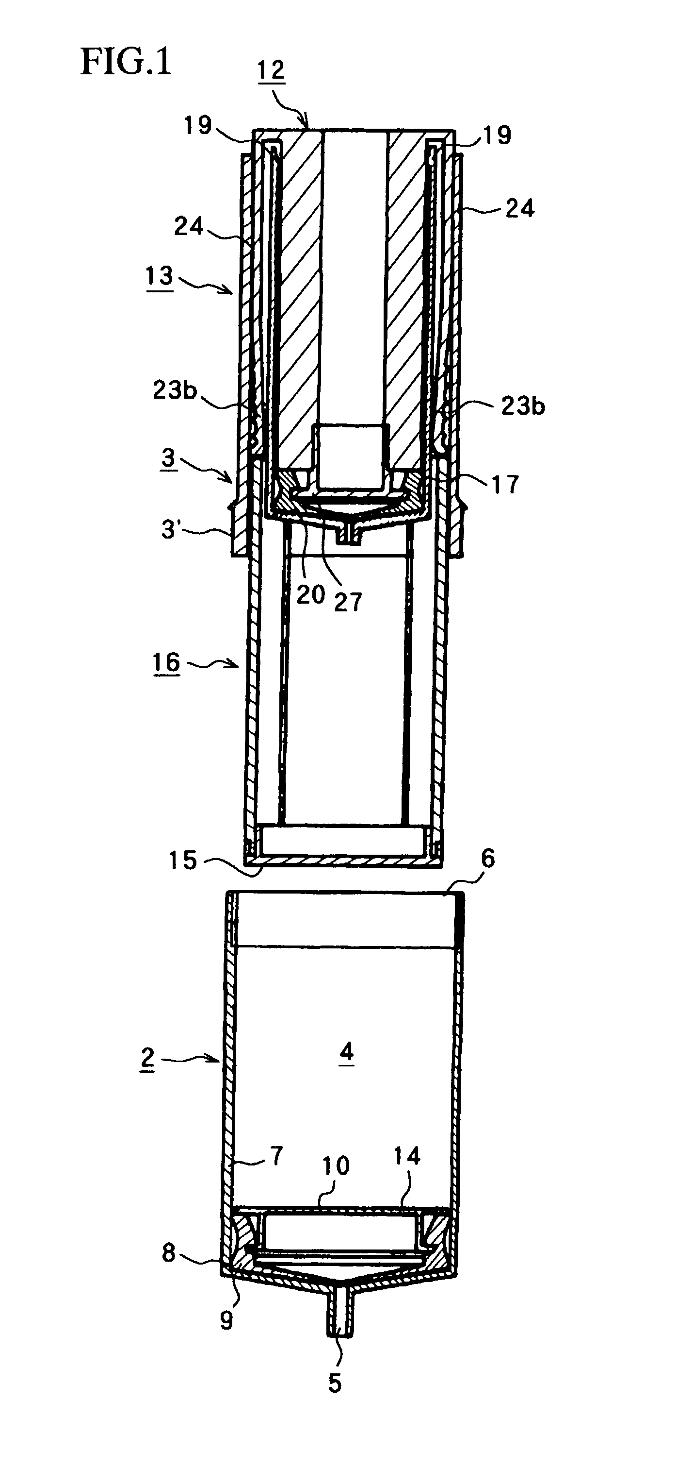
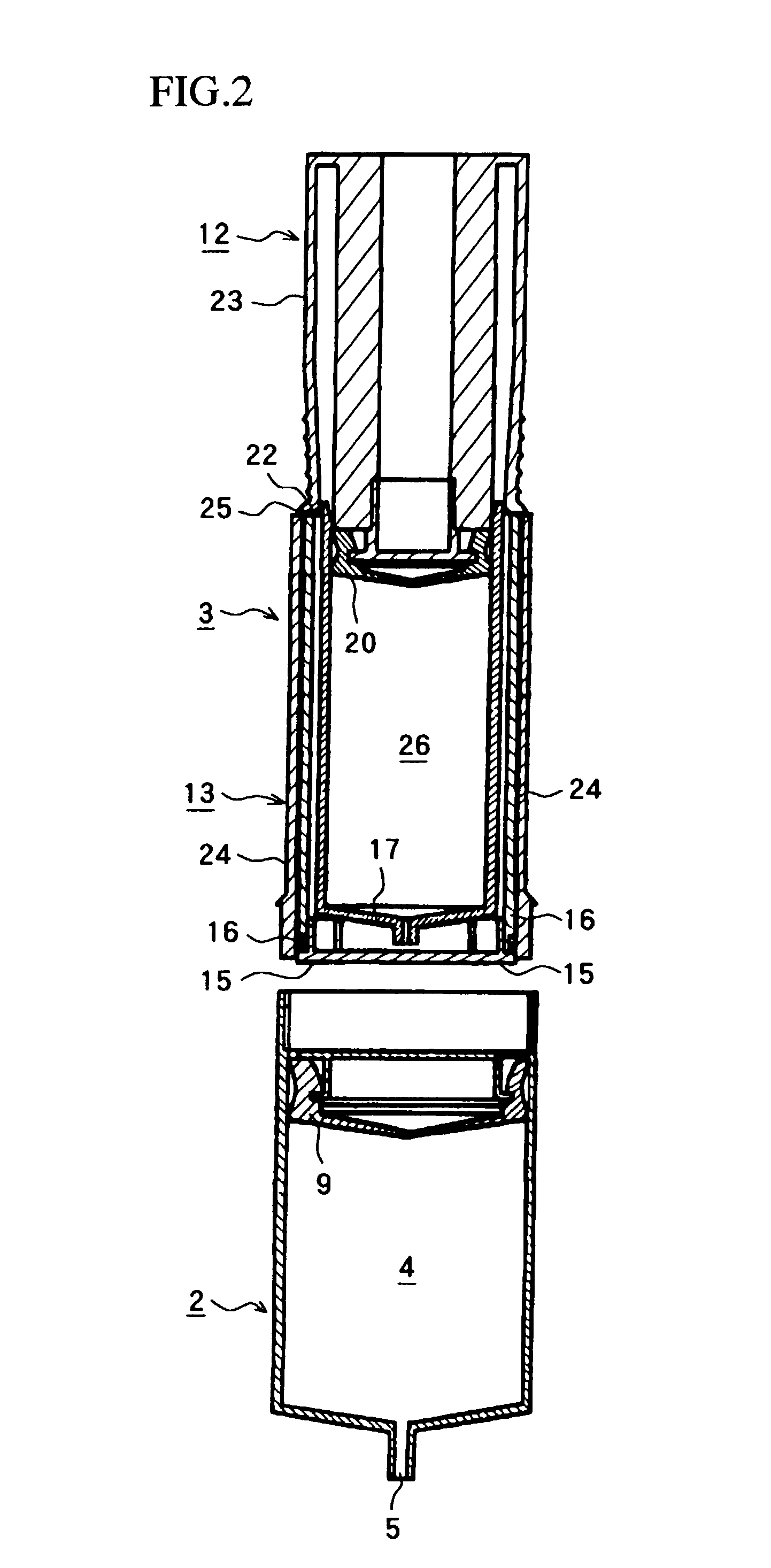
[0051] FIG. 1 to FIG. 6 show an example of a separation type infusion device as an embodiment of the infusion device of the present invention. An infusion device 1 of the present invention has a liquid syringe section 2 and a driving pump section 3.

[0052] As shown in FIG. 1, the liquid syringe section 2 is provided which has a liquid filling chamber 4 in which liquid is filled and, at one end (a bottom end in the drawing) of the chamber 4, a liquid infusion port 5 through which liquid passes when the liquid is infused, sucked, or the like. The liquid infusion port 5 has a protruding shape so that a liquid tube (not shown) or the like is mounted on a tip thereof in liquid infusion. Further, at the other end (an upper end in the drawing) of the liquid filling chamber 4, an opening 6 to be ...


PUM


Abstract

The invention relates to a continuous liquid infusion device which can be easily prepared for operation with small force, and can infuse liquid at constant infusion rate and amount over a long time. It comprises a liquid syringe section and a driving pump section mounted on the liquid syringe section, wherein sliding the pressing arm of the driving pump section upward leads to axially slides the piston in the negative pressure chamber to produce a negative pressure therein; and using returning force of the piston under the negative pressure, the liquid pushout plunger barrel is biased toward the upper edge of a pressing member through a locking member engaged with the piston so as to push out liquid in the liquid syringe from the liquid infusion port. Further, only the liquid syringe is disposable while the vacuum pump barrel on the driving side is good for repeated use (reusable).

Description

[0001] This application is a continuation application of International Application PCT / JP01 / 00890, filed Feb. 8, 2001, and designating the U.S.[0002] 1. Field of the Invention[0003] The present invention relates to a continuous liquid infusion device, and particularly to a continuous liquid infusion device which is simply preparable for operation with small force, easy to handle, and capable of infusing liquid at a predetermined infusion rate and amount over a long period of time.[0004] 2. Description of the Related Art[0005] In infusing liquid for treatment into human or animal bodies, liquid is continuously infused at a predetermined flow rate for a long time in some cases. For example, there are cases which require transfusion of a nutrition supplement solution or the like, or liquid infusion such as an anticoagulant compound, an anticancer compound, a demulcent, a local anesthesia compound, a blood sugar value adjusting compound, or the like in a solution state into a body of a ...

Claims


Application Information

Patent Timeline
Patent Type & Authority Applications(United States)
IPC IPC(8): A61M5/14A61M5/145A61M5/148
CPCA61M5/1408A61M2005/14513A61M5/14526
Inventor MINEZAKI, SUSUMUTAKAHASHI, HIROSHI
Owner ORCHIS
Why Eureka
Try Eureka