Production method of ceramic moldings and apparatus therefor

a technology of ceramic molding and production method, which is applied in the direction of dough shaping, manufacturing tools, applications, etc., can solve the problems of not being able to produce ceramic moldings smoothly, and producing honeycomb structures having excellent shapes,

Inactive Publication Date: 2002-11-14
DENSO CORP
View PDF0 Cites 22 Cited by
  • Summary
  • Abstract
  • Description
  • Claims
  • Application Information

AI Technical Summary

Problems solved by technology

Consequently, it is difficult in this case to produce a honeycomb structure having an excellent shape at a high production yield.
When those ceramic moldings which are difficult to mold, such as a honeycomb body having a reduced thickness, are molded, even the methods of the prior art technologies 1 and 2 cannot smoothly produce the ceramic moldings having an excellent shape because their shape correcting effect is too small.
If the shape defect of the molding is very serious,

Method used


Image

  • Production method of ceramic moldings and apparatus therefor
  • Production method of ceramic moldings and apparatus therefor
  • Production method of ceramic moldings and apparatus therefor

Examples


embodiment 1

[0050]

[0051] A production method and a production apparatus of ceramic moldings according to the first embodiment of the present invention will be explained with reference to FIGS. 1 to 6.

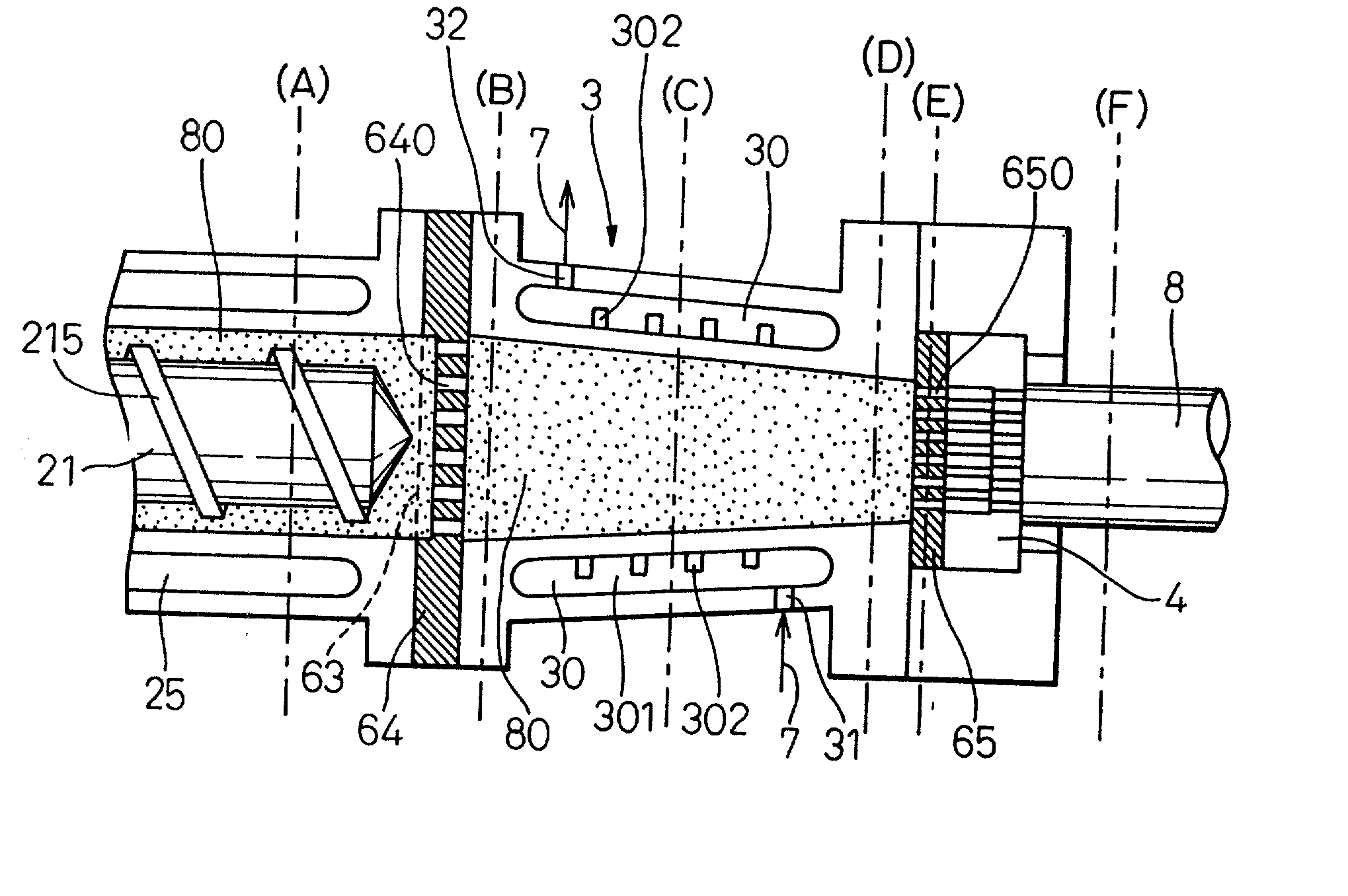
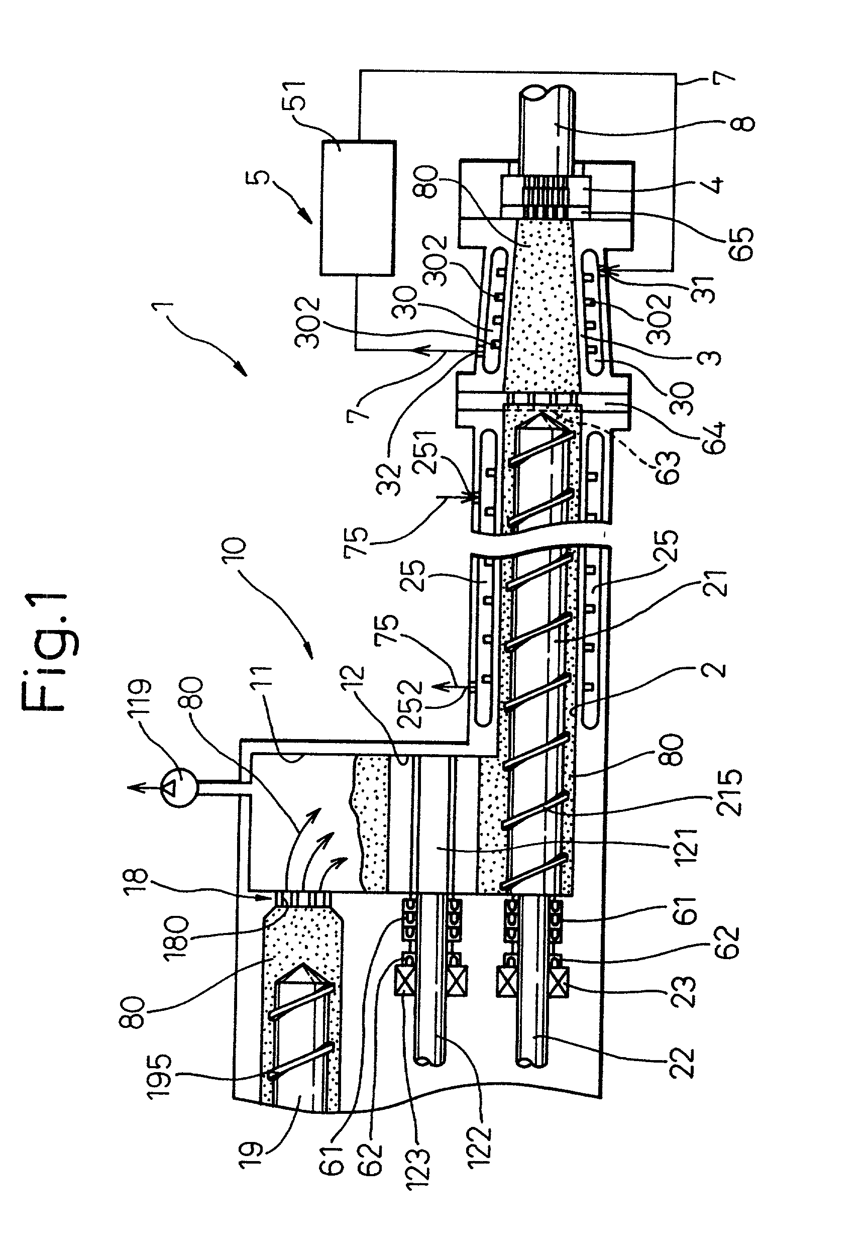
[0052] The production apparatus 1 of ceramic moldings of this embodiment includes a screw type extruder 10 and a mold 4 connected to the distal end of the extruder through a resistance pipe 3, as shown in FIG. 1. This apparatus extrudes the ceramic material 80, that is pressure-fed from the extruder 10 into the resistance pipe 3, from the mold 4 and produces a ceramic molding 8 having a desired shape.

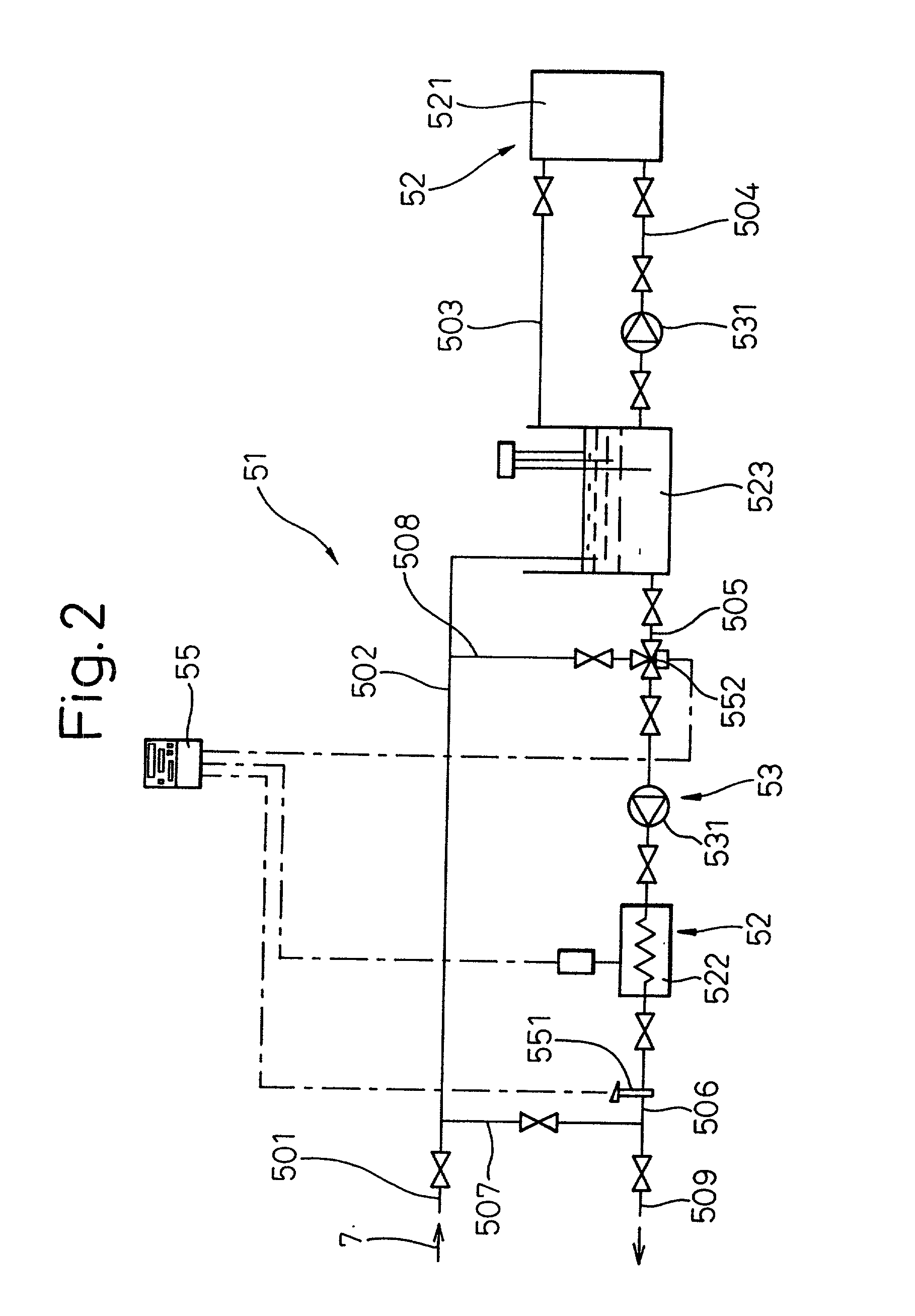
[0053] Material temperature regulation means 5 is disposed round the periphery of the resistance pipe 3 to heat or cool the ceramic material 80 that is pressure-fed from the extruder 10 into the resistance pipe 3. This material temperature regulation means 5 controls the shape of the ceramic molding 8 extruded.

[0054] Hereinafter, an explanation will be given in detail.

[0055] First, the ceramic molding ...

embodiment 2

[0087]

[0088] In this second embodiment, the shapes of the resistance pipe and the mold in the production apparatus 1 of the first embodiment are changed and a honeycomb structure 802 having a substantially elliptic sectional shape is produced, as shown in FIG. 7. More concretely, this embodiment uses a resistance pipe 39 the sectional shape of which changes from a round shape to a substantially elliptic shape and a mold 49 the slit shape of which is arranged in a substantially elliptic shape, as shown in FIGS. 8A and 8B. A fluid circulation passage comprising four partitioned spaces 391 to 394 are disposed round the resistance pipe 39 so that the heat medium 7 can be circulated through each of these spaces 391 to 394.

[0089] In this embodiment, two systems of medium supply circuits are disposed. A medium supply line 51a of the first system is connected in parallel with the upper and lower spaces 391 and 392 and the medium supply line 51b of the second system is connected in parallel ...


PUM

PropertyMeasurementUnit
Temperatureaaaaaaaaaa
Electrical resistanceaaaaaaaaaa

Abstract

In a method of producing a ceramic molding 8 having a desired shape by extruding a ceramic material 80 pressure-fed into a resistance pipe 3 from a mold 4 by using a production apparatus including a screw type extruder 10 and the mold 4 connected to the distal end of the extruder 10 through the resistance pipe 3, the ceramic material 80 pressure-fed from the extruder 10 into the resistance pipe 3 is heated or cooled from round the periphery of the resistance pipe 3 so as to control the shape of the ceramic molding 8 extruded from the mold 4.

Description

[0001] 1. Field of the Invention[0002] This invention relates to a method of, and an apparatus for, producing ceramic moldings such as ceramic honeycomb structures.[0003] 2. Description of the Related Art[0004] A ceramic honeycomb structure 8 having a large number of cells 88 partitioned by partitions 81, as shown in FIG. 12 of the accompanying drawings, has been used as a catalyst support of an exhaust gas purification device of an automobile. Ceramic moldings having a ceramic honeycomb structure are generally produced through extrusion molding.[0005] A production apparatus 9 for ceramic moldings according to the prior art includes a screw type extruder 91 and a mold 93 fitted to the distal end of the extruder 91 through a resistance pipe 92 as shown in FIG. 13. A ceramic material 80, that is pressure-fed from the extruder 91 into the resistance pipe 92 with the revolution of an extrusion screw 911, is extruded from the mold 93 as a ceramic molding having a desired shape. The extru...

Claims


Application Information

Patent Timeline
IPC IPC(8): B28B3/20B28B3/26
CPCB28B3/206B28B3/26B29C47/92B28B3/269B28B17/0072B28B3/2654B29K2103/04B29C48/022B29C48/395B29C48/69B29C48/834B29C48/86B29C48/865B29C48/87B29C48/92B29C2948/92209B29C2948/92447B29C2948/926B29C2948/92704B29C2948/92876B29C2948/92895B29C2948/92904B29C2948/92971
Inventor YAMAGUCHI, SATORUKATOU, HIROMIMATSUI, NOBUTOSHI
Owner DENSO CORP
Why Eureka
Try Eureka