Bone anchor inserters and methods

a bone anchor and inserter technology, applied in the field of surgical bone anchor inserters, can solve the problems of inefficiency of devices, surgeons can lose access to bored holes or seated bone screws, and the procedure is somewhat cumbersome, so as to reduce the length of bone clearance, reduce the size of the surgical incision, and reduce the effect of bone clearan

Inactive Publication Date: 2002-12-05
AMS RES CORP
View PDF99 Cites 150 Cited by
  • Summary
  • Abstract
  • Description
  • Claims
  • Application Information

AI Technical Summary

Benefits of technology

0017] The present invention comprises novel surgical bone anchor inserter devices and novel methods that may involve such devices. In one aspect, the inserter includes a battery-powered device with a distal portion that is significantly reduced in size. For example, ...

Problems solved by technology

Placing a bone anchor in a remote region of a patient presents a particular challenge for a surgeon.
Often, the intended location of the screw is surrounded by sensitive, vulnerable tissue such as arteries, nerves and veins.
This procedure is somewhat cumbersome and it is believed that surgeons can lose access to the bored hole or seated bone screw.
The device is inefficient in that it requires the user to squeeze the device multiple times in order to fully implant the screw.
Some users find the repeated squeezing awkward and difficult to use.
Control is believed to be another problem associated with the Precision Twist device.
It is believed that inaccurate placement of bone screws can lead to several complications, such as damage to the periosteum, increased infection rates (e.g. due to the damage), and lower suture pull out force for the sutures associated with the ...

Method used


Image

  • Bone anchor inserters and methods
  • Bone anchor inserters and methods
  • Bone anchor inserters and methods

Examples


example 1

Sling Procedure

[0126] Referring to FIGS. 7 through 9, surgical sling procedures for treating incontinence are generally illustrated. I.V. antibiotics may be administered prophylactically. The patient is placed in the lithotomy position and receives general, local or spinal anesthesia. After the patient has been prepped and draped, a Foley catheter (not shown) is placed in the bladder 6 and the balloon is inflated to approximately 20 cc. Pulling downward on the catheter, the balloon is palpated to identify the level of the bladder neck. Using this location as a reference point, the anterior vaginal wall of the vagina 2 is incised I to create exposure (e.g. from midurethra to bladder neck). A midline, inverted "U", or "T" incision may alternatively be performed.

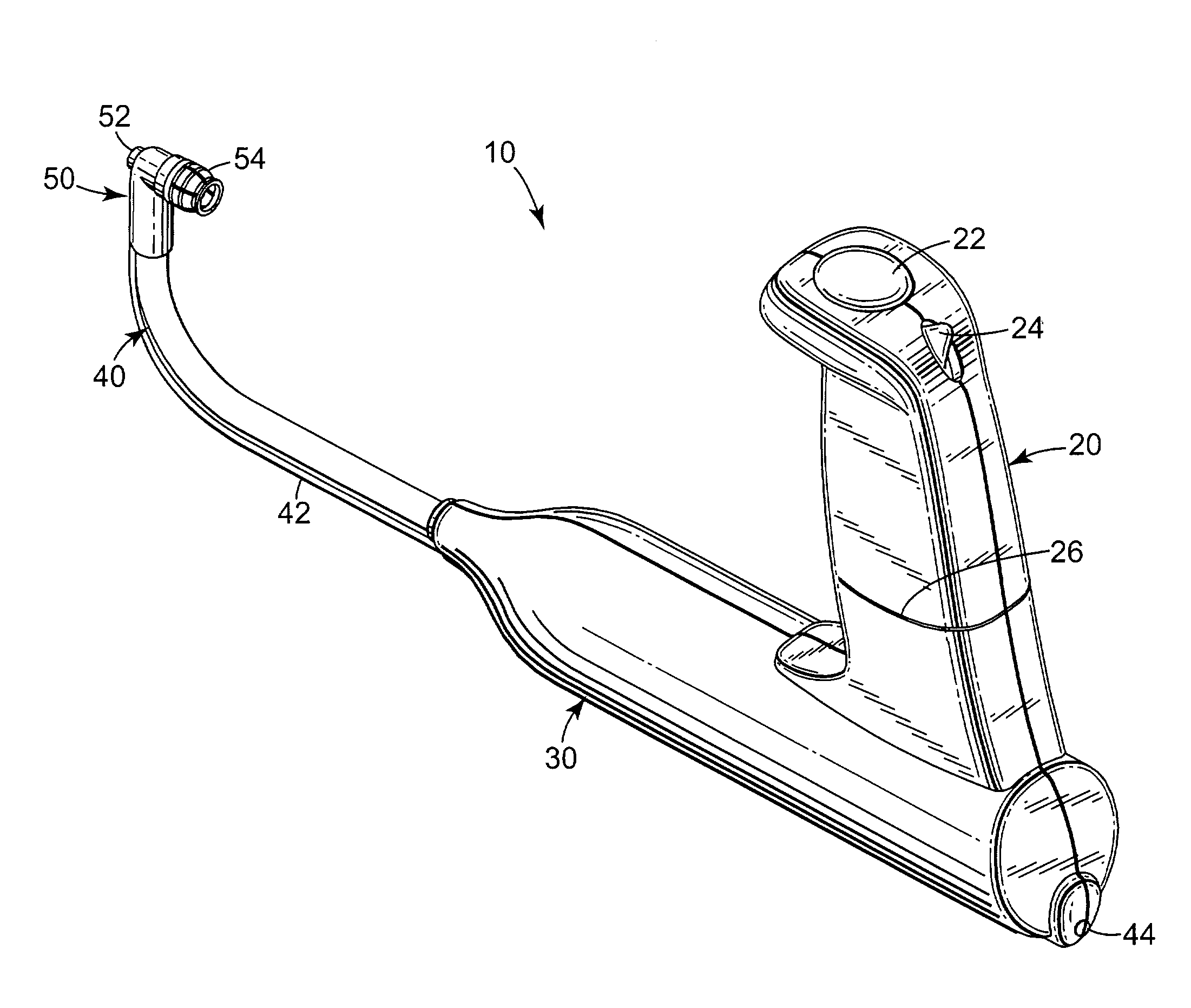
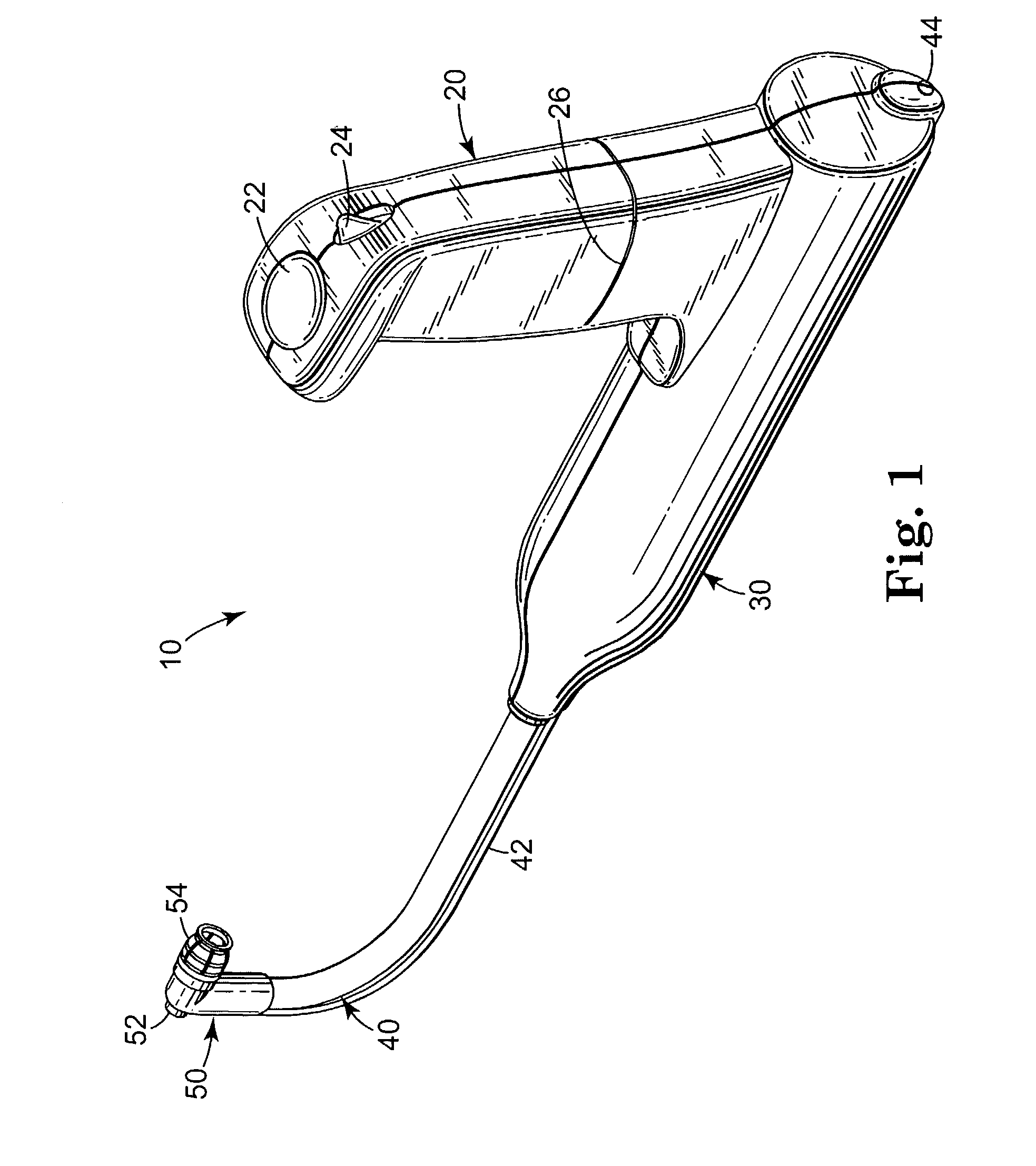
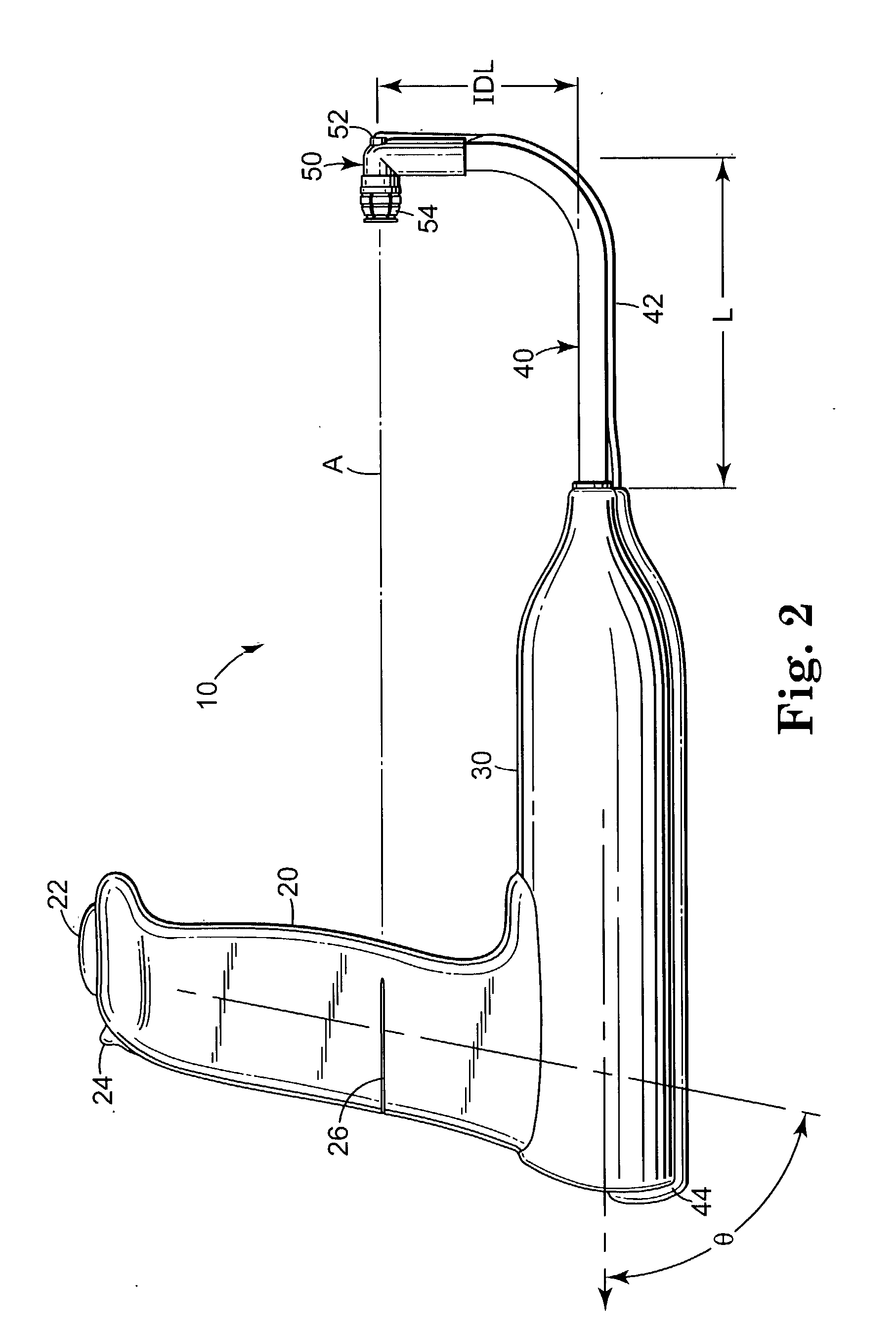
[0127] A defect of adequate size is optionally created to allow passage of the surgeon's index finger F alongside the inserter (e.g. 10 of FIGS. 1-6) in order to guide it into proper position on the posterior pubic bone 4. This...


PUM


Abstract

Bone anchor inserters are described. The inserters may be used in novel methods. Kits that include the novel inserters are also described.

Description

[0001] The present application is a continuation-in-part of U.S. Design patent application Ser. No. 29 / 151,465 filed Nov. 9, 2001 and claims priority to U.S. Provisional Application Serial No. 60 / 295,328 filed Jun. 1, 2001, and U.S. Provisional Application Serial No. 60 / 295,330 filed Jun. 1, 2001, and U.S. Provisional Application Serial No. 60 / 311,776 filed Aug. 10, 2001. The entire contents of the provisional patent applications and the design patent are herein incorporated by reference in their entirety.[0002] Bone anchors are used for a variety of surgical purposes. Orthopedic or soft tissue surgical procedures that utilize bone anchors are disclosed in U.S. Pat. Nos. 5,376,097, 5,572,342, 5,643,320, 5,741,282, and 5,980,558; percutaneous surgical procedures for treating incontinence are disclosed in U.S. Pat. Nos. 5,611,515, 5,836,314, 5,842,478 and 5,860,425; transvaginal surgical procedures for treating incontinence are disclosed in U.S. Pat. Nos. 5,972,000, 6,039,686, 6,053,9...

Claims


Application Information

Patent Timeline
IPC IPC(8): A61B17/00A61B17/04A61B17/88
CPCA61B17/0401A61B17/8891A61B2017/00734A61B2017/0409B25B21/004B25B13/481B25B17/00B25B21/002A61B2017/044
Inventor ANDERSON, KIMBERLY A.NEISZ, JOHANN J.ROCHELEAU, GARY A.LUND, ROBERT E.
Owner AMS RES CORP
Why Eureka
Try Eureka