
Data storage and access employing clustering

Inactive Publication Date: 2002-12-12
IBM CORP
View PDF61 Cites 65 Cited by
  • Summary
  • Abstract
  • Description
  • Claims
  • Application Information

AI Technical Summary

Benefits of technology

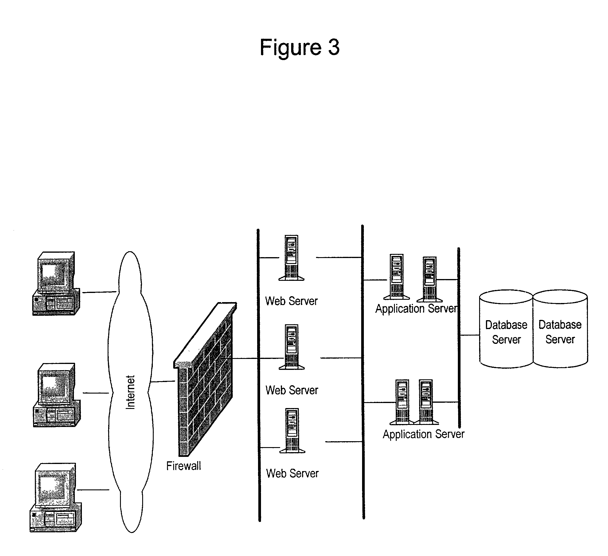
[0050] The system of the present invention comprises a Clustering System for data storage and data processing. The system includes a hardware or vertical scaling component and a horizontal or data scaling component. The Clustering System of the present invention surpasses the data handling capability of the three tier browser based system and can support millions of users through multiple sites. In a unique advantage of the present invention, commercial components are used to effectively scale to much greater sizes than such components were originally designed.
[0051] Generally, a central or system administrator based system contains data on all users of the system. When users enter the Clustering System through a login screen they are operating in the central cluster. As the user selects, for example, data representing a completed construction property such as a hotel or a property under construction, the users are pushed to one of a number of local clusters. This means that after the initial login each cluster only has to deal with a sub-set of users of the entire Clustering System.
[0052] Redundancy is built into the system by mirroring each server and having backup in case of failure. If one of the clusters were lost then the users would be pushed to another cluster. The Clustering System offers high contingency and scalability through its partitioned architecture.
[0053] In a further aspect of the system, a data partitioning model is utilized that splits up data so that no one piece of hardware is overloaded. When used with the Intelligent Business System described in co-pending U.S. patent application Ser. Nos. 10 / 021,661, 10 / 015,903, and 10 / 016,615, for example, each property may be given its own data server so that the efficiency of the storage component is increased. For example, a system could contain billions of documents (such as purchase orders (POs) and bids) but through data partitioning, the information is split up by property to avoid searching through endless tables of non-related entries.
[0054] A general representation of the system of the present invention is shown in FIG. 4. As shown therein, the central database server contains various sub-databases that span a number of properties and projects. As the user enters the application, they are operating within the central database, which is where all of the functionality in the first screen is performed. Such as:
[0059] To ensure dependability and eliminate single points of failure, each server is mirrored so that data and information can never be lost.

Problems solved by technology

Application code for the CPU to execute was difficult to write or change, and implementation was limited.
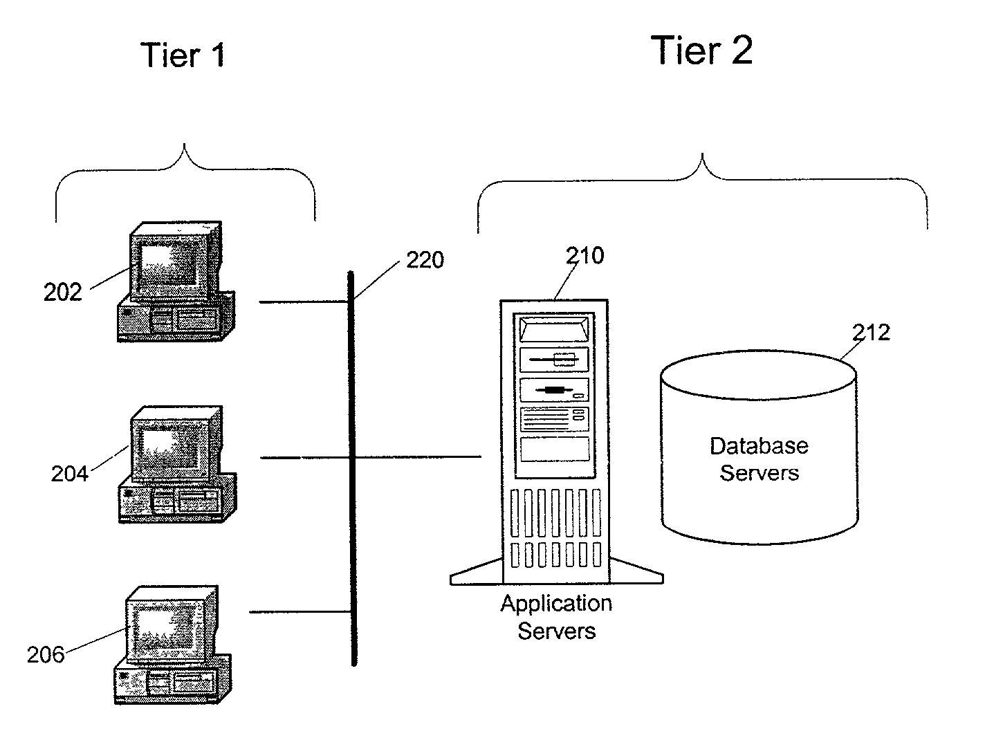
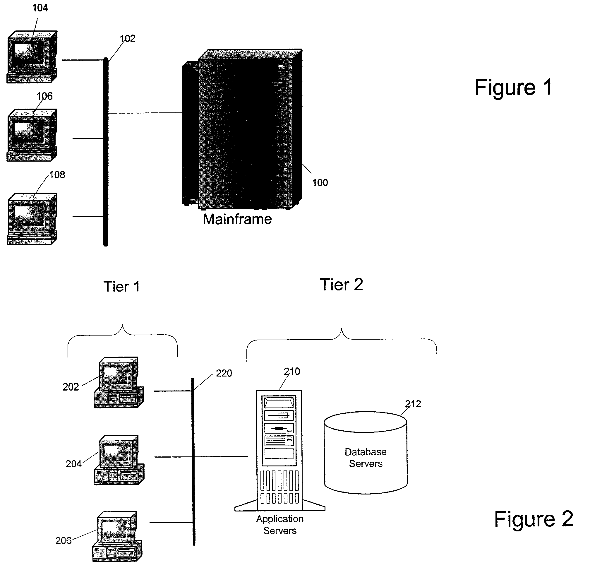
Client Server systems are problematic since PCs were easily overloaded by software applications, and software application updates required individual downloading via diskette or from the web.
Businesses, service providers and governments will need to manage tremendous amounts of information in an effective manner, and not all agencies will have the ability or the resources to command proprietary database structures to enable such database management.
While systems such as Networked Attached Storing (NAS) and Storage Area Networks (SANS) offer some performance and scalability, each as drawbacks.
NAS based applications are bandwidth limited, so that when the database or network access pipe reaches some upper limit, data access becomes problematic.
SANS generally lack the file sharing capabilities of NAS systems.
Horizontal scaling is absolutely required but can only take a non-proprietary architecture so far.
The problem with the master-slave model is that the slave is idle until it is promoted to become the master.
The problem with the master-master model is complexity.
The master-master replication strategy is an order of magnitude more difficult to design and implement.
This event would not even be detected until the systems attempted to push their changes to the other system, in which case the replication would have failed because the changes were considered a violation of business logic.
The failure would leave both systems out of sync and could cause data instabilities in other parts of the system until the problems are found and corrected.
Business Objects do not know the location of the data that they service.
Given that fact that there are many application servers and a client being re-routed to a wrong server would cause application failure because the state that was cached by the original application server would be unavailable to any other application server (except in the case of a single mirrored clustered machine).

Method used


Image

  • Data storage and access employing clustering
  • Data storage and access employing clustering
  • Data storage and access employing clustering

Examples


Embodiment Construction

has been presented for purposes of illustration and description. It is not intended to be exhaustive or to limit the invention to the precise form disclosed. Many modifications and variations are possible in light of the above teaching. The described embodiments were chosen in order to best explain the principles of the invention and its practical application to thereby enable others skilled in the art to best utilize the invention in various embodiments and with various modifications as are suited to the particular use contemplated. It is intended that the scope of the invention be defined by the claims appended hereto.


PUM


Abstract

A data management system operable between a set of presentation layer servers, a set of application servers and a set of data servers. The data management system includes: a session manager routing users to at least one of a plurality of presentation layer servers; an application manager coupling business applications provided by the business application servers responsive to user interaction with the presentation servers; and a data manager coupling business applications to at least one of a plurality of data sets.

Description

CLAIM OF PRIORITY[0001] This application claims the benefit of U.S. Provisional Application Serial No. 60 / 274,302, entitled "Intelligent Data Storage And Access Employing Central And Local Clusters", filed Mar. 8, 2001.[0002] 1. Field of the Invention[0003] The present invention is directed to providing a large amount of real time data to applications, and in particular, to providing a system which is both horizontally and vertically scalable to handle large amounts of data and provide such data to applications in real time.[0004] 2. Description of the Related Art[0005] The Internet provides individuals with access to information on a scale heretofore unknown. The quantity of such information is also growing at an ever-increasing rate. One consequence of this information explosion is the need to maintain and scale data in a database that is accessible to large numbers of people, and which contains millions if not billions of items. Such large scale database systems with the ability ...

Claims


Application Information

Patent Timeline
IPC IPC(8): G06F17/30
CPCG06F17/30893G06F16/972
Inventor SPENCER, HERMAN JR.
Owner IBM CORP
Learn More