Fast restoration in optical mesh network

a fast restoration and optical mesh technology, applied in transmission monitoring/testing/fault-measurement systems, transmission, fault recovery arrangements, etc., can solve the problems of large overhead message traffic, delay in restoration, traffic congestion of control data communication channels, etc., and achieve greater scalability and faster operation

Inactive Publication Date: 2002-12-19
NORTEL NETWORKS LTD
View PDF12 Cites 123 Cited by
  • Summary
  • Abstract
  • Description
  • Claims
  • Application Information

AI Technical Summary

Benefits of technology

0023] Another preferred feature of some of the embodiments involves having a node local to the fault make the choice of w

Problems solved by technology

Fibre cuts, and hardware/equipment failures are the main reasons why networks typically have some redundant capacity and a restoration scheme to make use of it.
In practice, advanced centralised techniques tend to generate large amounts of overhead message traffic, much of it from alarms generated as a consequence of the first fault.
This traffic may congest the control data communication channels.
Hence the restoration may be delayed, partly by the time needed for alarm correlation, to locate the fault or faults.
When carrying out restoration at the SONET level, it is necessary to access the SONET overhead data, which involves providing expensive receiver equipment, to convert an optical transmission signal to the electrical domain, for decoding.
The main disadvantage of the first of these options, the predetermined protection paths, is that it requires 100% redundancy, since any sharing of pred

Method used


Image

  • Fast restoration in optical mesh network
  • Fast restoration in optical mesh network
  • Fast restoration in optical mesh network

Examples


Embodiment Construction

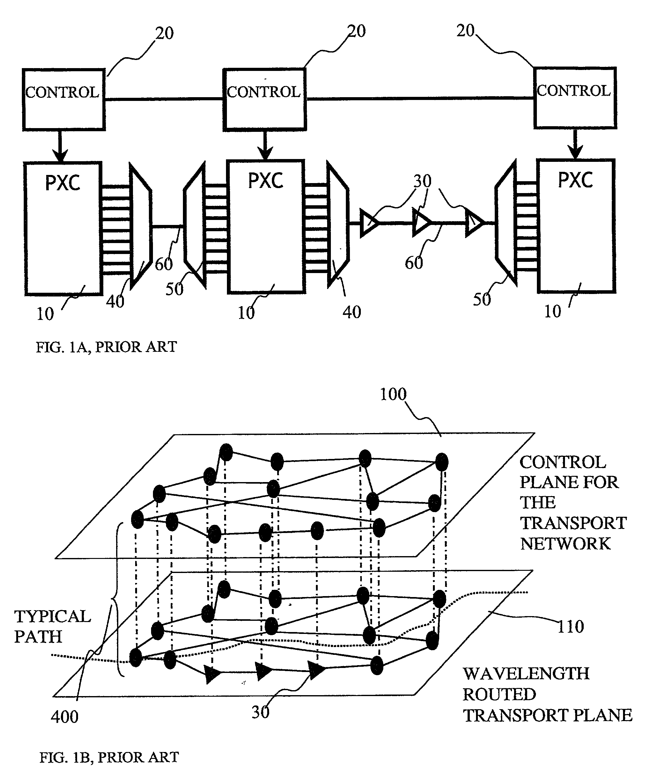
[0044] By way of introduction to the examples of how to implement the above mentioned features, first of all, a typical network will be described briefly. FIG. 1 shows in schematic form, a type of network, in which embodiments of the present invention may be applied. Part of such a network is shown in FIG. 1A.

FIGS. 1A, 1B, Wavelength Routed Optical Network.

[0045] FIG. 1A shows some of the principal elements in schematic form of a conventional wavelength routed optical network. Photonic cross connects (PXC) 10 are located at many or each of the nodes of the network. Three are shown, though in practice there may be a mesh of tens or hundreds of nodes inter-connected in a mesh, depending on required traffic characteristics. The cross-connects may be implemented using electronic switching, or optical switching, or a mixture. Wavelengths, or bands of wavelengths, or groups of wavelengths may be switched between different links in the network to enable them to reach their desired destinat...


PUM


Abstract

A wavelength division multiplexed optical network has a restoration process to re-route one or more of the wavelengths, by dynamically determining possible restoration routes, and re-routing each wavelength along a chosen one of the possible restoration routes. A distributed dynamic search for restoration routes down to the optical layer, for wavelengths, gives faster and more scalable restoration than reconfiguring routing tables and enables much better utilisation of bandwidth than using predetermined restoration paths.

Description

[0001] The invention relates to wavelength division multiplexed optical networks, to nodes for such networks, to restoration processes for such networks, to software for carrying out such processes, to signals sent when carrying out such processes, and to methods of transmitting data traffic over such networks arranged to carry out such restoration processes.BACKGROUND TO THE INVENTION[0002] Restoration is a growing area of concern in high bandwidth optical networks. Restoration involves re-routing a data signal onto a spare path. Fibre cuts, and hardware / equipment failures are the main reasons why networks typically have some redundant capacity and a restoration scheme to make use of it. It is possible to provide for re-routing the data traffic at various levels in the well-known 7 layer OSI model. For example, at layer 3, IP Packets may be re-sent, at layer 2 / 3, ATM (asynchronous transfer mode) circuits may be restored on to different routes, and ATM cells may be buffered. At laye...

Claims


Application Information

Patent Timeline
IPC IPC(8): H04B10/02H04B10/08H04J14/02
CPCH04B10/03H04B10/07H04B10/0793H04J14/0228H04J14/0284H04J14/0295H04J14/0241H04J14/0227
Inventor LU, XIANGDONG, SONG
Owner NORTEL NETWORKS LTD
Why Eureka
Try Eureka