Method of manufacturing microlens array and microlens array

a manufacturing method and microlens technology, applied in the field of microlens arrays, can solve the problems of inability to produce microlens arrays with a focal length about the same as the diameter of the lens, and the inability to realize high-performance optical coupling elements

Inactive Publication Date: 2002-12-26
PANASONIC CORP
View PDF0 Cites 51 Cited by
  • Summary
  • Abstract
  • Description
  • Claims
  • Application Information

AI Technical Summary

Problems solved by technology

The above-illustrated ion exchange diffusion method is suitable for forming a microlens having a diameter of from a several tens of microns to a several hundreds of microns; however, problems have been found with the method in manufacture of a microlens having a relatively large lens diameter or a lens effective diameter of from a several hundreds of microns to a several millimeters.
Thus, in the ion exchange diffusion method, it is difficult to prepare lenses of a wide range of sizes having diameters from a several tens of microns to a several millimeters and, also, it is impossible to produce a microlens array having a focal length that is about the same as that of the diameter of the lens.
Therefore, downsized and high-performance optical coupling elements have not been realized by the use of the ion exchange diffusion method.

Method used


Image

  • Method of manufacturing microlens array and microlens array
  • Method of manufacturing microlens array and microlens array
  • Method of manufacturing microlens array and microlens array

Examples


first embodiment

[0060] (First Embodiment)

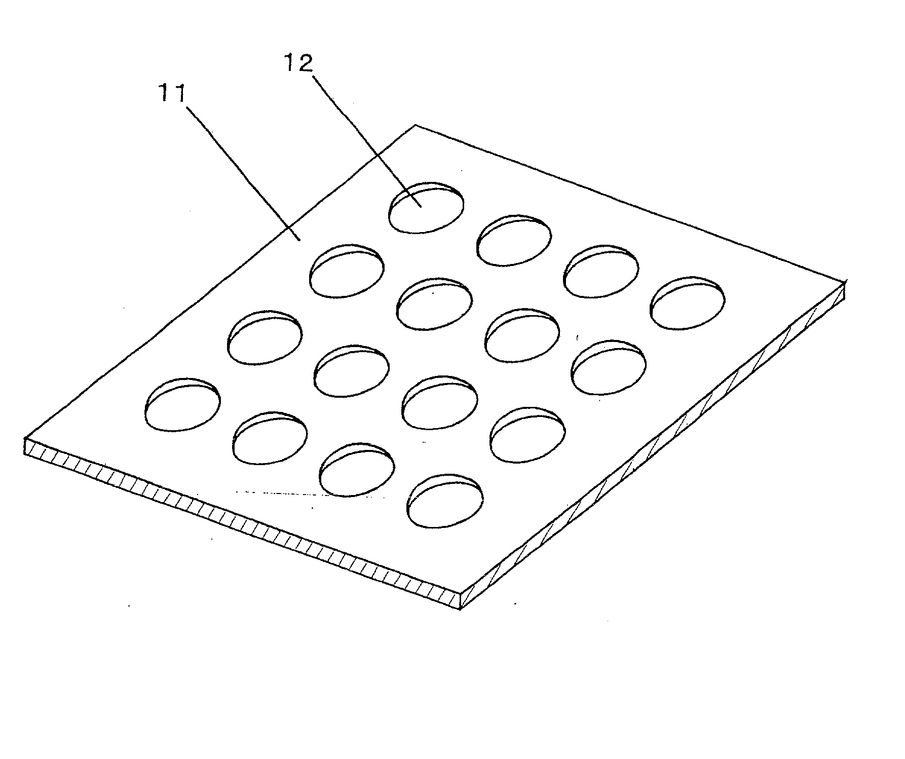
[0061] FIG. 1 is a perspective view showing a microlens array according to a first embodiment of the present invention. As shown in FIG. 1, the microlens array in the first embodiment comprises a substrate 11 in which a plurality of through holes are provided and convex lenses 12 arranged on each of the through holes in the substrate 11, wherein a diameter of each of the convex lenses is from about a several tens of microns to about a several millimeters.

[0062] The convex lenses 12 have light transmitting properties and they are formed from a curable liquefied resin material or a thermoplastic material or a glass material that can be cured on the substrate 11.

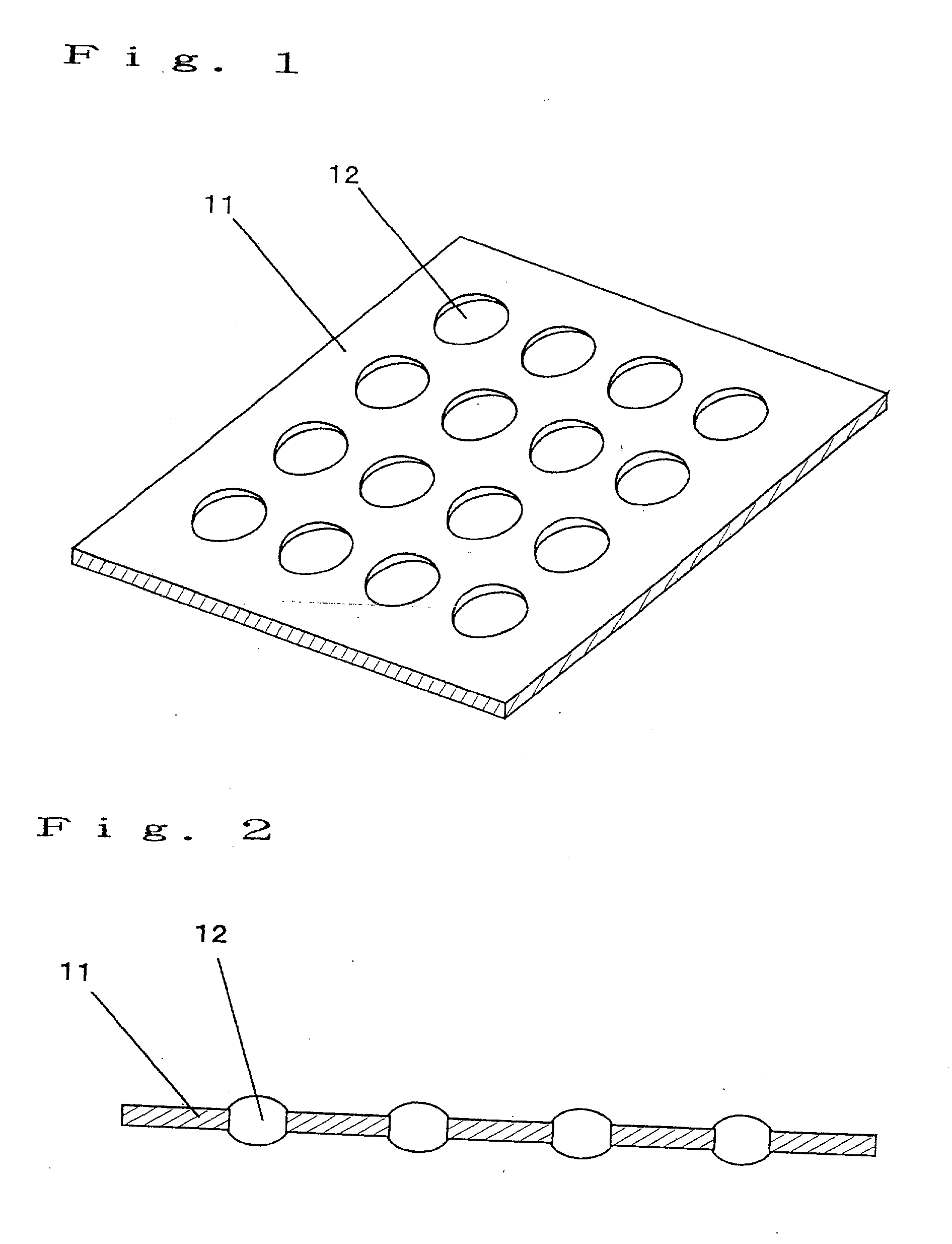
[0063] FIG. 2 is a cross-sectional view of the microlens array according to the first embodiment of the present invention described above with reference to FIG. 1, showing a state wherein the convex lenses are respectively disposed at the through holes on the substrate 11.

[0064] The microlens array acco...

second embodiment

[0069] (Second Embodiment)

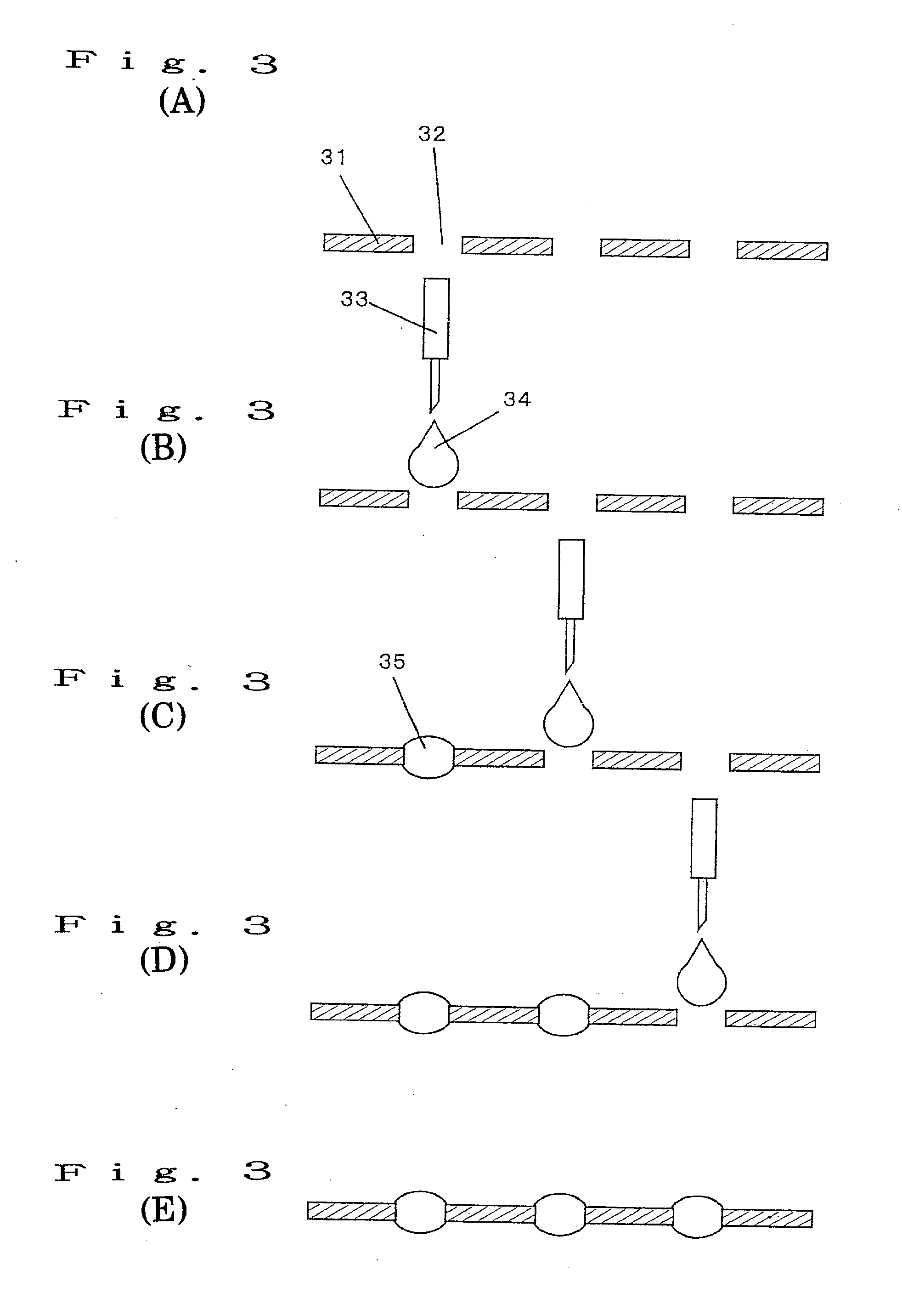
[0070] FIGS. 3A to 3E are illustrations for a method of manufacturing microlens array according to a second embodiment of the present invention. The method of manufacturing microlens array of the second embodiment in the case of using a glass material for a substrate 31 and an adhesive resin material having light transmitting properties as a material for lenses 35 as shown in FIGS. 3A to 3E will be described in detail below.

[0071] As shown in FIG. 3A, through holes 32 are formed on a substrate 31 precisely by employing various fine processing techniques. The fine processing techniques to be employed may be an ultraprecise cutting, a laser processing, a focusing ion beam processing, a laser etching, a microdischarging, an electron beam writing.

[0072] Then, as shown in FIG. 3B, an adhesive material 34 is dropped from drop nozzles 33. A viscosity of the adhesive material 34 is so selected that the adhesive material stays in the through holes 32 without falling...

third embodiment

[0074] (Third Embodiment)

[0075] A method of manufacturing microlens array according to a third embodiment of the present invention that is illustrated in FIGS. 4A to 4C will be described below. The process illustrated in FIGS. 4A to 4C is different from that illustrated in FIGS. 3A to 3E by a nozzle unit 44 that is formed by integrating a plurality of nozzles in order to shorten a time required for the production. By the use of such integrated dropping nozzles 44, a microlens array comprising the plurality of convex lenses can be two-dimensionally produced in a remarkably short period and effectively.


PUM

PropertyMeasurementUnit
sizesaaaaaaaaaa
contact angleaaaaaaaaaa
transmittivityaaaaaaaaaa

Abstract

A method of manufacturing a microlens array comprising forming microlenses by dropping or injecting to a plurality of through holes formed on a substrate a liquefied lens material so as to dispose the lens material at each of the through holes, the lens material being curable and has a predetermined transmittivity and a predetermined viscosity.

Description

[0001] 1. Field of the Invention[0002] The present invention relates to a microlens array typically used in the fields of optical communication and optical packaging for coupling light emitted from a light source to an optical fiber or an optical waveguide, converting light emitted from the optical fiber or the optical waveguide into parallel rays or so focusing light beams to enter the optical fiber or the optical waveguide in an optical coupling system.[0003] 2. Related Art of the Invention[0004] The microlens in general represents a fine lens having a lens diameter of not more than a several millimeters. Various methods relating to the microlens array including methods for manufacturing the same have been proposed in the art. The ion exchange diffusion method is widely known as a method for manufacturing the microlens array. In the ion exchange diffusion method, a dopant ion is selectively diffused on a multicomponent glass substrate.[0005] The conventional ion exchange diffusion...

Claims


Application Information

Patent Timeline
Patent Type & Authority Applications(United States)
IPC IPC(8): G02B3/00
CPCB29D11/00375G02B3/0018H01L27/14685G02B3/0068H01L27/14627G02B3/0056
Inventor ITOH, NOBUKI
Owner PANASONIC CORP
Why Eureka
Try Eureka