Apparatus and method for monitoring performance of minimally invasive direct cardiac compression

a technology of direct cardiac compression and monitoring apparatus, which is applied in the field of medical devices and methods, can solve problems such as preventing the operator from receiving tactile feedback from the devi

Inactive Publication Date: 2003-01-02
THERACARDIA
View PDF0 Cites 8 Cited by
  • Summary
  • Abstract
  • Description
  • Claims
  • Application Information

AI Technical Summary

Benefits of technology

[0014] The signal processor, which receives the force transducer signal, will usually comprise a digital processor, an analog processor, or a high voltage amplifier. The signal processor may be powered by a battery or other suitable power source. The power source may be automatically turned on when the applied force exceeds a given threshold force, the threshold force ranging from 0.1 lbs. to 15 lbs., and automatically turned off after a period of device non-activity, typically after 15 minutes, so as to limit any wasted battery use.
[0015] The signal processor may comprise circuitry or software, such as EPROM and timer chips, that compares the applied force signal to an optimal force value and produces a feedback message to increase, decrease, or maintain the actual applied force. Optimal force application values for minimally invasive direct cardiac massage will preferably be in a range from 5 lbs. to 15 lbs., more preferably from 8 lbs. to 12 lbs. The circuitry or software may additionally convert the force transducer signal to a heart compression rate signal. The circuity may further compare the applied compression rate to an optimal compression rate value, and produce a feedback message to increase, decrease, or maintain the actual applied compression rate. Optimal compression rate values will preferably be in a range from 60 bpm (beats per minute) to 120 bpm, more preferably from 80 bpm to 100 bpm. In some instances, a multiple array of force transducers may be coupled to the handle to produce multiple force transducer signals. The signal processor in turn receives and processes such signals and produces a feedback message to adjust or maintain a location or angle of force application.
[0016] The display receives the feedback messages from the signal processor and produces a human decipherable indication based on the feedback messages to let the treating individual immediately know whether too high, too low, or acceptable force and / or compression rate is being applied, and / or whether the location and / or angle of force application is correct. It will be appreciated that the output from the signal processor may be displayed in any number of ways. For example, the human decipherable indication may be visual, such as LED (light emitting diode) lights, discrete value digital readouts, flashing lights, and the like. Alternatively, the human decipherable indication may be a sound system, such as an audible alarm, a pacing signal, or voice commands. Hence, the devices and methods of the present invention give a perceptible indication when appropriate compression forces and / or compression rates are applied, thereby minimizing the possibility that insufficient or excessive compression strokes are being applied during a given cardiac massage procedure. Another advantage of the present invention is that the device may be used by persons of minimal experience or training, while still allowing for control and optimization of cardiac massage performance by the treating person within the correct operating parameters (force, compression rate, etc.). Moreover, the use of such electronic monitoring provides an enhanced tactile feel to a treating person, as conventional mechanical gauges employing a compressible member often have a large compliance, thereby impeding any tactile feedback to an operator of the device.

Problems solved by technology

Moreover, the use of such electronic monitoring provides an enhanced tactile feel to a treating person, as conventional mechanical gauges employing a compressible member often have a large compliance, thereby impeding any tactile feedback to an operator of the device.

Method used


Image

  • Apparatus and method for monitoring performance of minimally invasive direct cardiac compression
  • Apparatus and method for monitoring performance of minimally invasive direct cardiac compression
  • Apparatus and method for monitoring performance of minimally invasive direct cardiac compression

Examples


Embodiment Construction

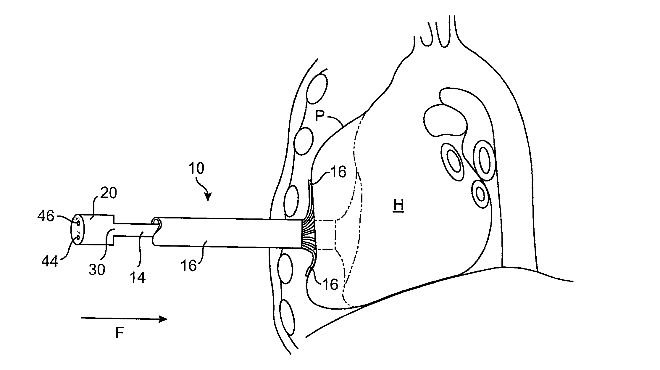
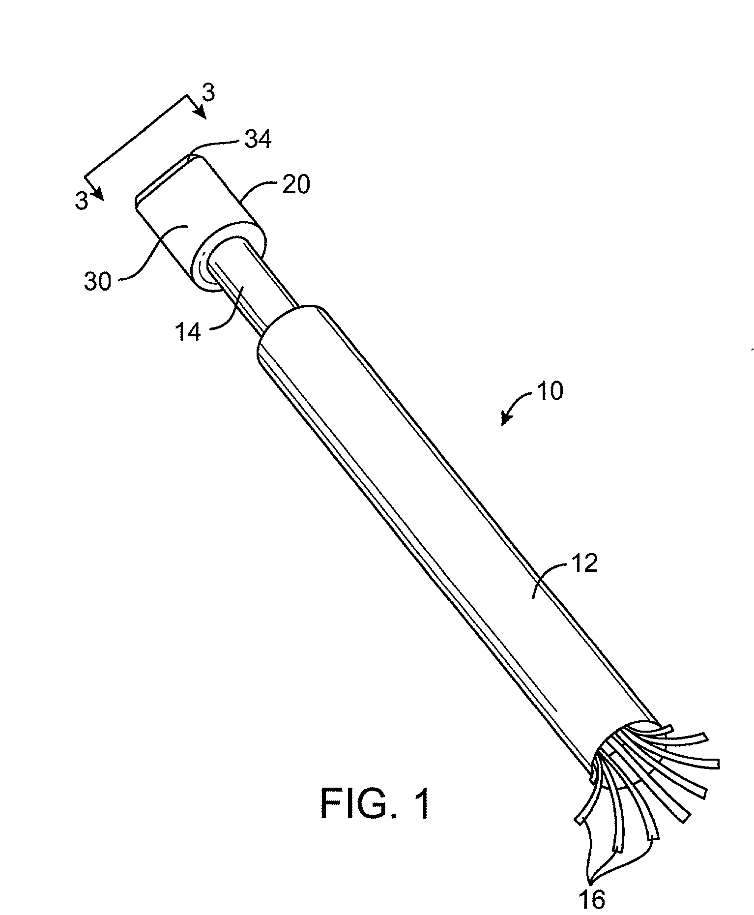
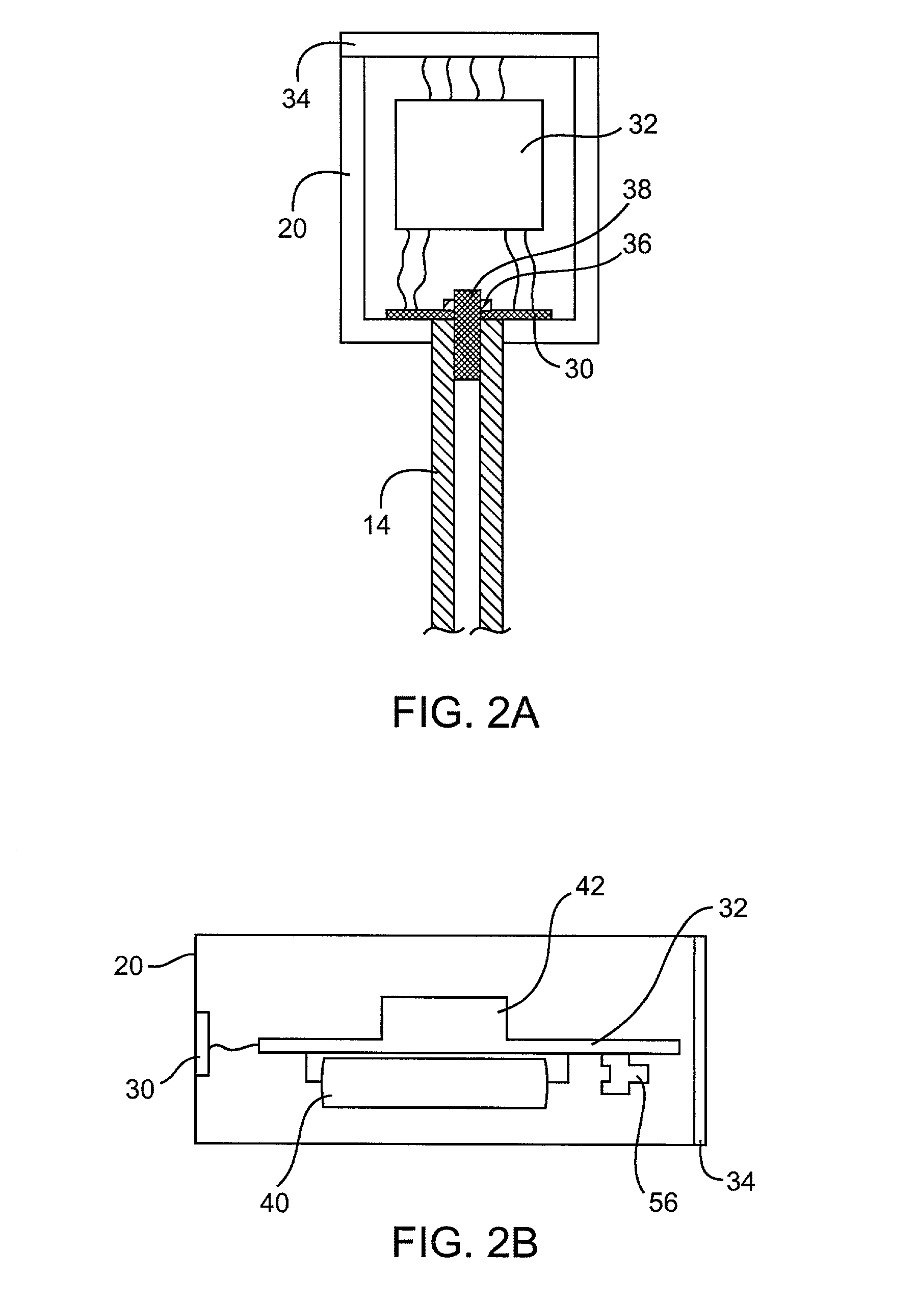
[0031] Referring now to FIG. 1, an exemplary device 10 constructed in accordance with the principles of the present invention generally comprises a shaft 14, a structure 16 attached to a distal end of the shaft adapted to contact the pericardium or other heart surface to compress the heart, and a force transducer 30 coupled to the proximal end of the shaft 14 to produce a signal which corresponds to an amount of force applied through the shaft 14 to the heart. A signal processor 32 receives the force transducer 30 signal and produces an output corresponding to the applied force. A display 34 receives the output of the signal processor 32 and produces a human decipherable indication based on the applied force. It will be appreciated that the following depictions are for illustration purposes only and does not necessarily reflect the actual shape, size, or dimensions of the minimally invasive direct cardiac massage device 10. This applies to all depictions hereinafter.

[0032] The devic...


PUM


Abstract

The present invention provides devices and methods for monitoring performance of minimally invasive direct cardiac massage. In particular, the present invention provides devices and methods which greatly facilitate proper performance of minimally invasive direct cardiac compression. Devices according to the present invention may comprise a handle, having a proximal end and a distal end, a structure attached to a distal end of the handle adapted to contact the pericardium or other heart surface to compress the heart, and a force transducer coupled to the handle and / or the structure to produce a signal which corresponds to an amount of force applied through the handle to the heart. A signal processor receives the force transducer signal and produces an output corresponding to the applied force. A display receives the output of the signal processor and produces a human decipherable indication based on the applied force.

Description

[0001] 1. Field of the Invention[0002] The present invention relates generally to medical devices and methods. More particularly, the present invention relates to devices and methods for monitoring performance of minimally invasive direct cardiac massage.[0003] Sudden cardiac arrest is a leading cause of death in most industrial societies. While in many cases it is theoretically possible to re-establish cardiac function, irreversible damage to vital organs, particularly the brain and the heart itself, will usually occur prior to restoration of normal cardiac activity.[0004] A number of techniques have been developed to provide artificial circulation of blood to oxygenate the heart and brain during the period between cardiac arrest and restoration of normal cardiac activity. Prior to the 1960's, open chest cardiac massage (OCM) was a standard treatment for sudden cardiac arrest. Open chest cardiac massage, as its name implies, involved opening a patient's chest and manually squeezing...

Claims


Application Information

Patent Timeline
Patent Type & Authority Applications(United States)
IPC IPC(8): A61B19/00A61M60/191A61M60/289A61M60/538
CPCA61B2019/464A61M1/1068A61B2090/064A61M60/289A61M60/538A61M60/191
Inventor BRENNEMAN, RODNEY A.HALILI, REYNALDO B. JR.
Owner THERACARDIA
Why Eureka
Try Eureka