Gas flushing system for use in lithographic apparatus

a technology of lithographic apparatus and gas flushing, which is applied in the field of lithographic apparatus, can solve the problems of excessive operating costs and inacceptable intensity loss

Inactive Publication Date: 2003-01-09
ASML NETHERLANDS BV
View PDF9 Cites 48 Cited by
  • Summary
  • Abstract
  • Description
  • Claims
  • Application Information

AI Technical Summary

Problems solved by technology

However, such wavelengths are strongly absorbed by normal atmospheric air leading to unacceptable loss of intensity as the beam traverses the apparatus.
To enclose the entire apparatus and operate in vacuum would introduce unacceptable delays in wafer and re...

Method used


Image

  • Gas flushing system for use in lithographic apparatus
  • Gas flushing system for use in lithographic apparatus
  • Gas flushing system for use in lithographic apparatus

Examples


Embodiment Construction

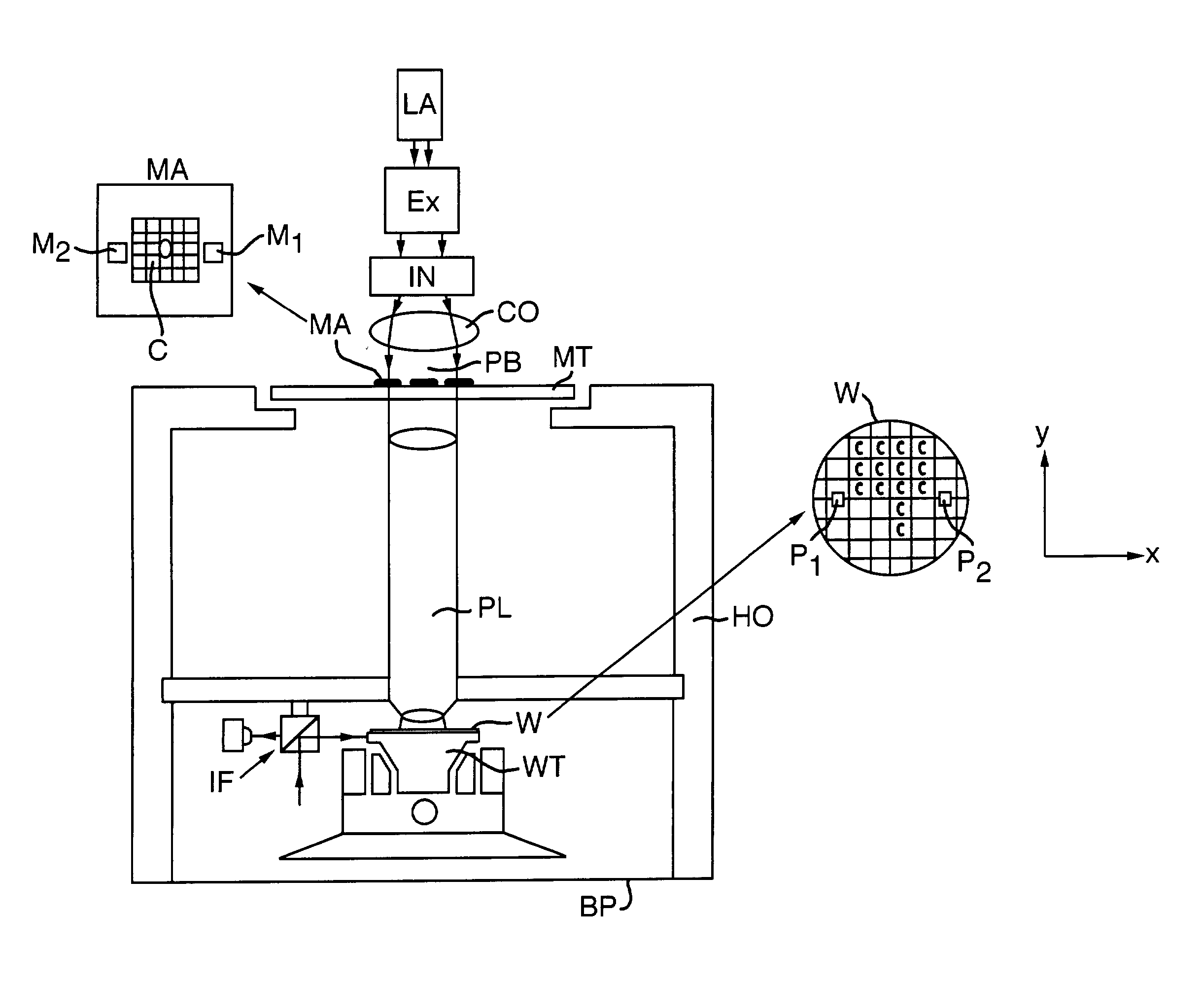
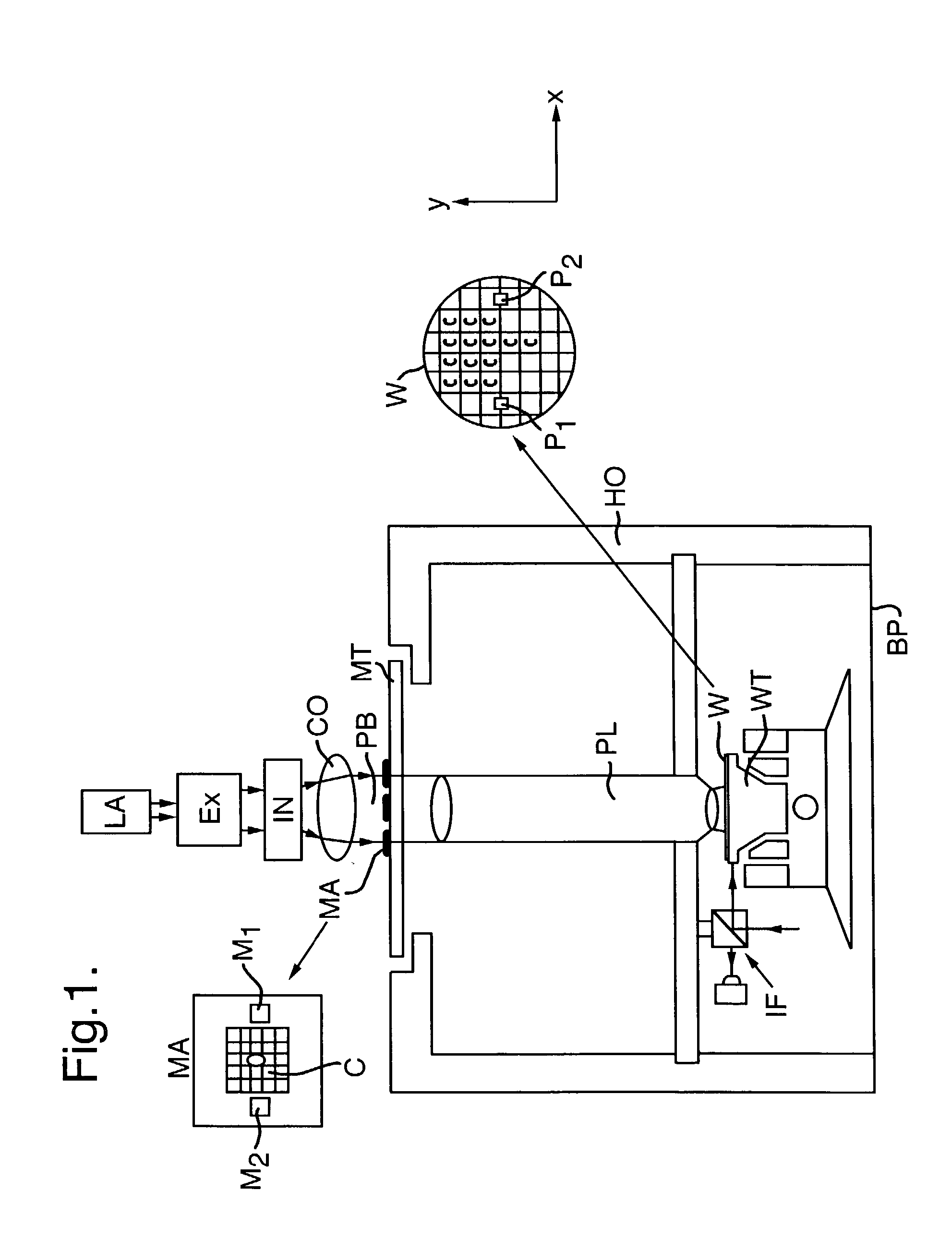
[0039] FIG. 1 schematically depicts a lithographic projection apparatus according to the invention. The apparatus comprises:

[0040] a radiation system LA, Ex, IN, CO for supplying a projection beam PB of radiation;

[0041] a first object table (mask table) MT for holding a mask MA (e.g. a reticle), and connected to first a positioning device M.sub.1, M.sub.2 for accurately positioning the mask with respect to a projection system PL;

[0042] a second object table (substrate table) WT for holding a substrate W (e.g. a resist-coated silicon wafer), and connected to a second positioning device P.sub.1, P.sub.2 for accurately positioning the substrate with respect to the projection system PL;

[0043] the projection system ("lens") PL for imaging an irradiated portion of the mask MA onto a target portion C (die) of the substrate W.

[0044] As here depicted, the apparatus is of a transmissive type (i.e. has a transmissive mask). However, in general, it may also be of a reflective type, for example....


PUM


Abstract

In a lithographic apparatus using exposure radiation of a relatively short wavelength, e.g. 157 or 126 nm, a laminar flow of N2 is provided across parts of the beam path in or adjacent to moving components of the apparatus. A variety of structures may be used to provide the laminar flow including a screen, a settling chamber, an angled inlet port and a flow path having increasing cross-sectional area.

Description

[0001] This application is a continuation-in-part of U.S. patent application Ser. No. 09 / 704,581, filed Nov. 3, 2000, which is herein incorporated by reference in its entirety.BACKGROUND FO THE INVENTION[0002] 1. Field of the Invention[0003] The present invention relates generally to lithographic apparatus, and more particularly, to lithographic apparatus incorporating a gas flushing system.[0004] 2. Description of the Related Art[0005] In general, lithographic projection apparatus include a radiation system for supplying a projection beam of radiation, a first object table for holding a mask, a second object table for holding a substrate, and a projection system for imaging an irradiated portion of the mask onto a target portion of the substrate.[0006] For the sake of simplicity, the projection system may hereinafter be referred to as the "lens"; however, this term should be broadly interpreted as encompassing various types of projection system, including refractive optics, reflect...

Claims


Application Information

Patent Timeline
IPC IPC(8): G03F7/20
CPCG03F7/70716G03F7/70858G03F7/70866G03F7/70933G03F7/70983
Inventor VAN EMPEL, TJARKO ADRIAAN RUDOLFSCHRIJVER, RAYMOND LAURENTIUS JOHANNESJACOBS, JOHANNES ANDREAS HENRICUS MARIAKEMPER, NICOLAAS RUDOLFKOPPELAARS, NICOLAAS FRANCISCUS
Owner ASML NETHERLANDS BV
Why Eureka
Try Eureka