Instrumented insole

a technology of insoles and instruments, applied in the field of instruments, can solve the problems of reduced walking velocity and disability, inconvenient routine clinical rehabilitation, and high cost of such equipmen

Inactive Publication Date: 2003-01-09
CATHOLIC UNIV OF AMERICA
View PDF0 Cites 319 Cited by
  • Summary
  • Abstract
  • Description
  • Claims
  • Application Information

AI Technical Summary

Problems solved by technology

A reduction in push-off power is therefore usually accompanied by a shortened stride, giving rise to decreased walking velocity and disability (Gage, 1991).
Unfortunately, such measurements are complex and require the services of a full gait laboratory, usually having motion analysis equipment and force platforms.
The expense and complexity of such equipment is prohibitive for routine clinical rehabilitation, and therefore is generally confined to teh relatively few centers of excellence in universitie...

Method used


Image

  • Instrumented insole
  • Instrumented insole
  • Instrumented insole

Examples


example 1

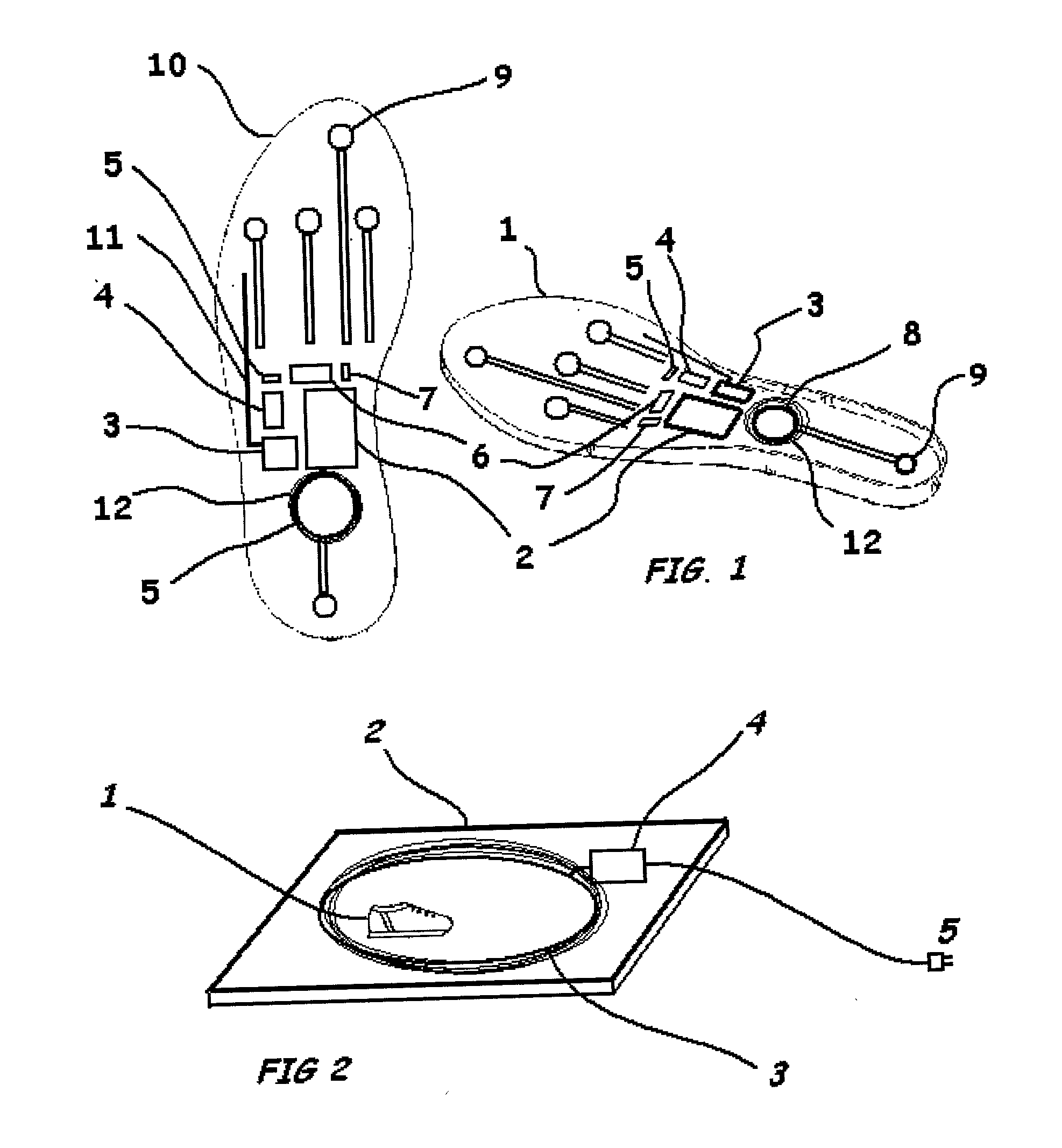
[0019] Methodology: The device to be developed is shown in FIG. 9. The force sensors are placed along the insole, such that they will detect force applied during the push-off phase. The solid state gyro (Type ENC-03JA, Murata, Japan) is mounted nearby (its location is not critical) to detect the angular velocity of the foot. Since the distance of the force sensors to the ankle-joint is known from the dimensions of the insole, the moment of force and angular velocity of the foot can be calculated. A necessary assumption is that the shank (lower-leg) of the subject is relatively stationary, with the foot angular velocity then being a close approximation of the ankle velocity. This is normally the case in both normal and pathological gait.

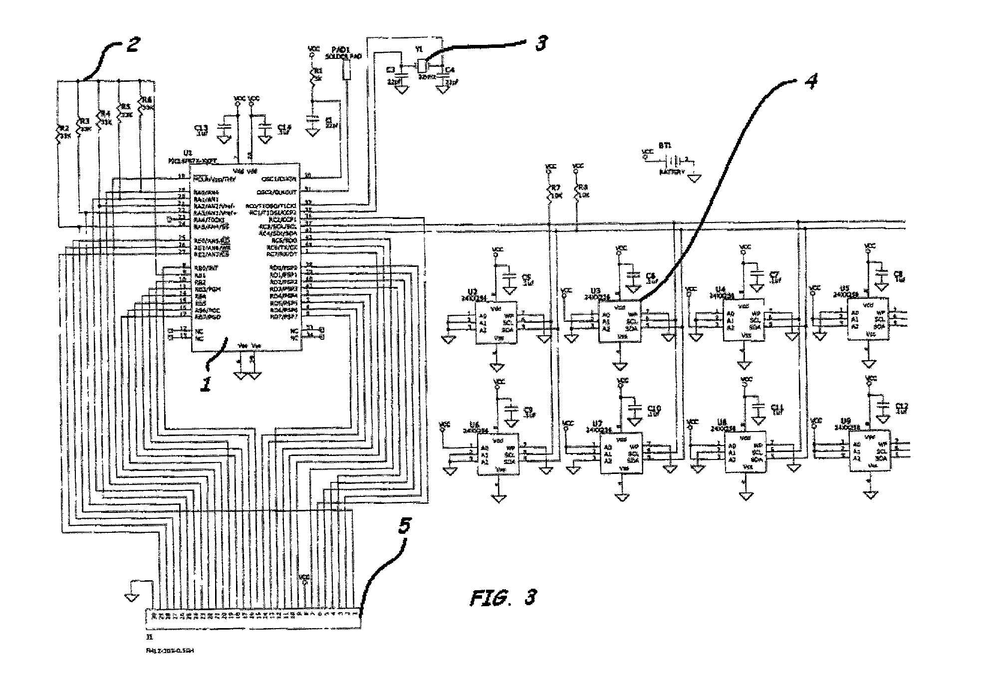
[0020] Electronics and Signal Processing: The force sensors require charge-amplifier. The charge from each sensor can be multiplexed before amplification, so that only a single amplifier is required, which will be initially housed in a small box on a ...

example

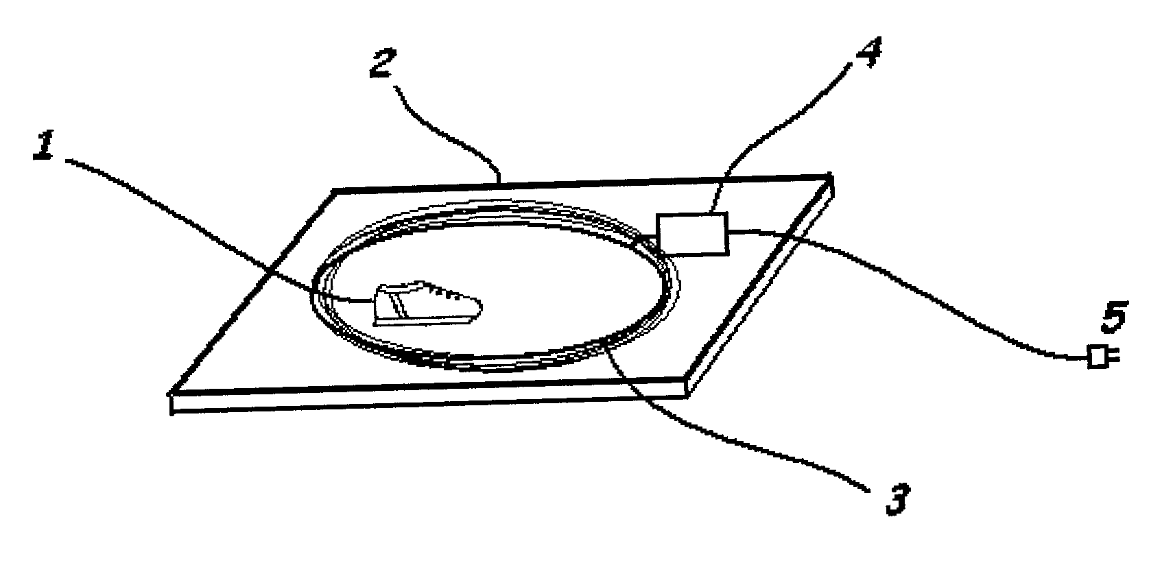
[0022] Method: The solid-state gyro sensor (Type ENC03JA, Murata, Japan) was mounted in a Pelite insole (FIG. 1). Its location in the instep was selected so as to be unaffected by flexing of the sole, and it was aligned transversely, such that it was most sensitive to angular velocity about the talo-crural joint. The subject then underwent a standard 3D gait analysis, using a Vicon motion analysis system (Oxford Metrics, Oxford, UK). The Vicon Clinical Manager (VCM) model (5) was used, with markers on the second metatarsal, lateral malleolus and lateral femoral condyle determining the foot and ankle joint angles. The output of the gyro sensor was recorded simultaneously. The subject was asked to walk slowly (0.65 m / s), in order to simulate a pathological gait. Several steps were recorded.

[0023] Results: The output of the gyro sensor closely tracked the angular velocity of the foot, as measured by the Vicon motion analysis system (FIG. 2). The objective of this study was to compare t...


PUM


Abstract

A combination of sensors, including solid-state gyros and force-sensitive resistors, are mounted in an insole suitable for insertion into a shoe. Data from the sensors is recorded by an in situ Programmable Interface Controller (PIC), logged into on-board EEPROM/Flash memory and relayed to a base station computer via a miniature telemetry transmitter triggered by RFID tagging. Software then uses this data to compute the cadence and ankle power of the subject, as well as other parameters, in order to analyze and assess the gait and activity of the subject.

Description

[0001] This application includes material described in U.S. Provisional Patent Application No. 60 / 213,981, entitled "Instrumented Insole," filed Jun. 24, 2000, and is entitled to the benefits of the filing date thereof.[0002] This application makes reference to U.S. Provisional Patent Application No. 60 / 213,981, entitled "Instrumented Insole," filed Jun. 24, 2000. This application is hereby incorporated by reference.BACKGROUND OF INVENTION[0003] Computerized Gait Analysis, using video-based techniques, has provided useful insights into the biomechanical cause of gait abnormalities and other movement disorders. One very common finding in a variety of clinical disorders is a reduction in ankle power at push-off (Winter, 1991). This power burst is chiefly responsible for the propulsion of the leg into its swing phase, and is thus highly correlated with the length of stride. A reduction in push-off power is therefore usually accompanied by a shortened stride, giving rise to decreased wa...

Claims


Application Information

Patent Timeline
IPC IPC(8): A61B5/00A61B5/103A63B24/00A63B69/00G01C22/00G01P1/12G01P15/00
CPCA61B5/0002A61B5/1038A61B5/4528A61B2560/0214A63B69/0028A63B2208/12A63B2220/40A63B2220/51A63F2300/105G01C22/006G01P1/127G01P15/00A61B5/4023A43B17/00A43B3/44
Inventor KIRTLEY, CHRIS
Owner CATHOLIC UNIV OF AMERICA
Why Eureka
Try Eureka