Pellets and method for producing the same

a technology of pellets and piping, applied in the direction of presses, manufacturing tools, furniture, etc., can solve the problems of filmy plastics, clogging the inside of the piping of the material simply subjected to crushing process, and low processing efficiency

Inactive Publication Date: 2003-01-30
NIPPON KOKAN KK
View PDF2 Cites 27 Cited by
  • Summary
  • Abstract
  • Description
  • Claims
  • Application Information

AI Technical Summary

Problems solved by technology

However, problems can occur with, particularly, filmy plastics.
Since the filmy plastics have a lower bulk density in comparison with that of a solid (lump) plastics, the material simply subjected to a crushing process tends to clog the inside of a piping during the pneumatic transportation.
since the method uses a batch process, the processing efficiency is low;
As a result of experiments performed by the inventors, however, the granular plastics formed by performing a preliminary process for the filmy plastics according to the above-described conventional method was found to have an insufficient strength.
As such, the granular plastic moldings tend to collapse in stages, for example, handling after processing and pneumatic transportation.
The collapse causes fluffy matters that can easily cause problems of, for example, clogging the inside of piping during, for example, pneumatic transportation and injection through tuyeres.
As such, appropriate granular plastic moldings cannot be obtained.
In addition, the granular plastic moldings, which have a low strength and hence tend to collapse, are poor as an injection raw material since they have a low burning efficiency.
That is, since a residence time of the plastics in the raceway is very short, the burning efficiency is reduced.

Method used


Image

  • Pellets and method for producing the same
  • Pellets and method for producing the same
  • Pellets and method for producing the same

Examples


embodiment 1

[0059] Embodiment 1

[0060] The inventors of the present invention carried out the research regarding causes for not being able to obtain a granular plastic moldings that have a sufficiently high strength and an improving measure therefore. As a result, the inventors obtained knowledge as described below in items (A) to (C).

[0061] (A) Granular plastic moldings granulated only from filmy plastics are formed of a plastics solidified after the plastics were semi-melted or melted. In this case, however, a sufficiently high strength cannot be obtained. A cause for the above is considered that the granular plastic moldings do not include a solid component that effectively functions as nucleuses for preserving the strength of the grain strength.

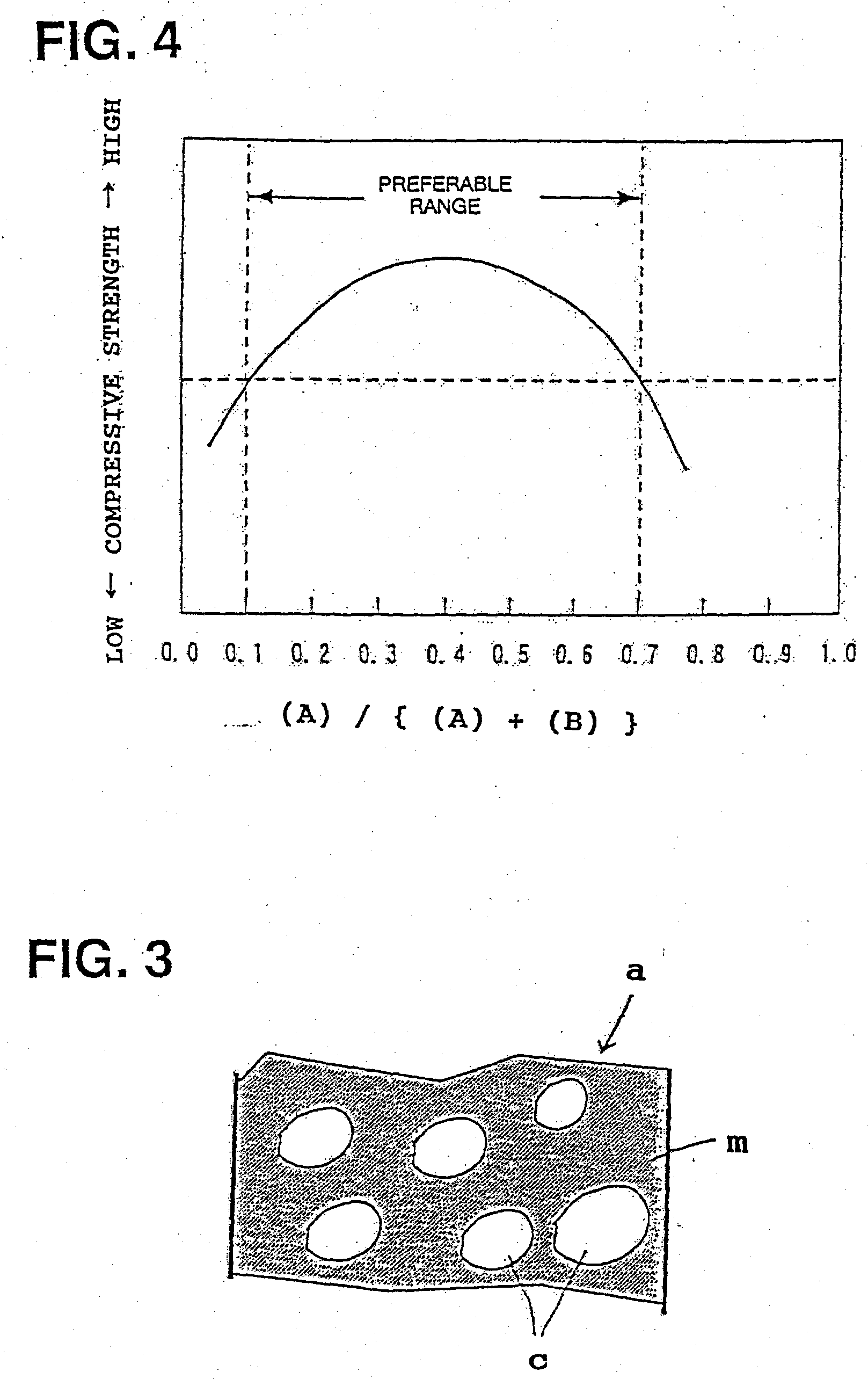
[0062] (B) On the other hand, when solid plastics and filmy plastics are mixed at an appropriate ratio and the mixture is pelletized into granular plastic moldings, the strength of the granular plastic moldings can be significantly increased. The gran...

embodiment 2

[0162] Embodiment 2

[0163] The inventors found that only controlling one of the grain strength and the grain diameter is not sufficient to improve the burning rate in a race way of a furnace. For example, according to the aforementioned control, the pellets cannot be fed to reach inside of the raceway; and even when the pellets can be fed to reach the raceway, the pellets are broken / collapsed while it is dispersed in hot air, thereby reducing the burning rate. From the above, it was found that the burning rate of the pellets can be improved by controlling both the strength and grain diameter of the pellets. Specifically, for injection to the furnace, the strength of the pellets is controlled so that the pellets can reach a predetermined zone in the furnace raceway; and the grain diameter of the pellets is controlled sufficient to be fed at a flow rate not lower than a limiting flow rate.

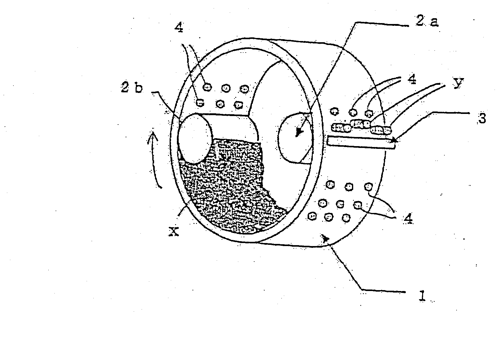
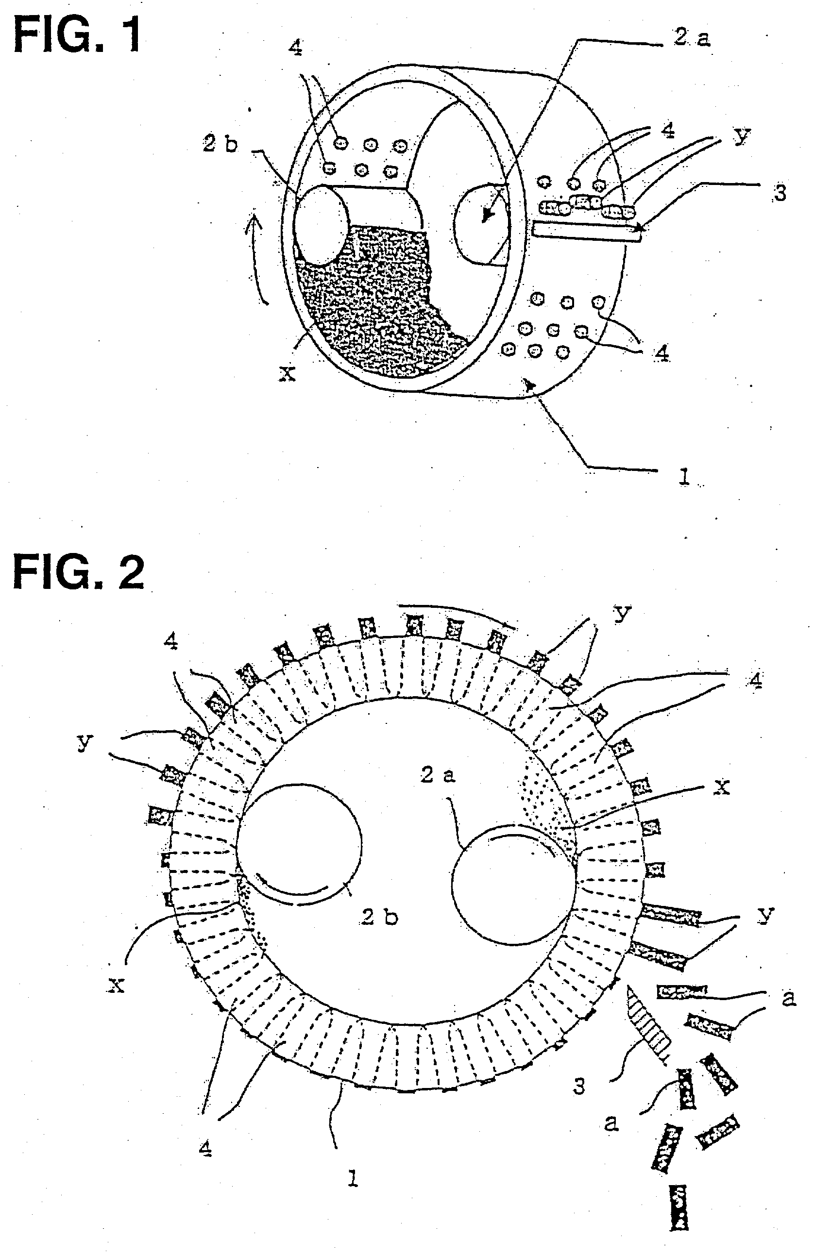
[0164] In addition, the inventors found the following. Using the ring-die pelletizer capable of gr...

example 1

[0202] First, the pellets of the above-described invention were compared with conventional pellets. The conventional pellets was produced according to a conventional method in which a synthetic-resin-based material was cut or crushed using a high-speed rotary bladed wheel, the synthetic resin material is semi-melted by frictional heat caused in the cutting or crushing operation, the semi-melted synthetic resin material is quickly cooled to be solidified, and the material is crushed using a rotary bladed wheel simultaneously with the solidification. When the thus-produced conventional pellets was injected through a blast-furnace tuyere, since the strength of the pellets is low, the time in which the pellets resides in a raceway was very short, and the burning efficiency was therefore low. On the other hand, however, the pellets of the above-described invention, which contains the synthetic resin material and has the melt-solidified surface, was produced by controlling the strength an...


PUM

PropertyMeasurementUnit
melting pointaaaaaaaaaa
weight ratioaaaaaaaaaa
thicknessaaaaaaaaaa

Abstract

Waste plastics including solid plastics, thin plastics, and foamy plastics are fed into a ring die of an extrusion molding machine. The waste plastics are either semi-melted or melted, and are then extruded onto an outer circumferential surface the ring die through die cavities. Thus, granular plastic moldings are extruded onto the outer circumferential surface of the ring die through the die cavities, and are then cut or scraped from the outer circumferential surface of the ring die. The pellets have a melt-solidified surface, and have a strength sufficient to reach a predetermine zone in a raceway of a furnace and a grain diameter sufficient to be fed at a velocity higher than a limiting velocity thereof during injection to the furnace.

Description

[0001] The present invention relates to a method for producing pellets by using waste plastics (plastics-based wastes) collected as general wastes and industrial wastes, and to pellets produced by to the method. More specifically, the present invention relates to pellets to be used as a raw material which is injected into a blast furnace, a cement kiln, or the like, and to a method for producing the pellets.DESCRIPTION OF THE RELATED ARTS[0002] When waste plastics are used as, for example, an injection raw material for a blast furnace, the waste plastics are pneumatically transported to tuyeres and are then injected into the blast furnace through the tuyeres. The waste plastics are therefore preliminarily processed into pellets that have a grain size and a bulk density to be appropriate for pneumatic transportation and injection into the blast furnace. However, problems can occur with, particularly, filmy plastics. Since the filmy plastics have a lower bulk density in comparison wit...

Claims


Application Information

Patent Timeline
Patent Type & Authority Applications(United States)
IPC IPC(8): B01J2/20B29B17/00B30B11/20C10L5/48C21B5/02
CPCB01J2/20B29B17/0026B29B17/0036B29B2017/0456B29B2017/0496B30B11/201Y10T428/2927C10L5/48C21B5/023C21B5/026Y02E50/10Y02E50/30C10L5/363B29B9/06B30B11/227Y02W30/62B29B17/00
Inventor SUGAYOSHI, TETSUROTOMIOKA, KOICHIISHIGURO, HIROKIOGAKI, YOJINAKAMURA, HIDEOKONISHI, TAKESHITERADA, KANEONEMOTO, KENICHIWAKAMATSU, SHINICHINAKATANI, HIROSHIOYANAGI, YASUAKIKANATANI, GENJIASANUMA, MINORUTOHMA, ICHIROABE, SEIICHI
Owner NIPPON KOKAN KK
Why Eureka
Try Eureka