Method and system for moving equipment into and through an underground well

a technology of equipment and transportation system, which is applied in the direction of sealing/packing, drilling pipes, and wellbore/well accessories, etc., can solve the problems of reducing the amount of oil and/or gas that can be produced through the well, requiring complex transportation systems, and requiring complicated procedures

Inactive Publication Date: 2003-02-13
SHELL OIL CO
View PDF0 Cites 26 Cited by
  • Summary
  • Abstract
  • Description
  • Claims
  • Application Information

AI Technical Summary

Benefits of technology

[0006] It is a further object of the present invention to provide a method and system for transporting equipment through an underground well which are able to transport and assemble and / or disassemble complex equipment assemblies in a well with a minimum of interruption of other operations.

Problems solved by technology

In underground oil and / or gas production wells transportation of equipment generally requires complex procedures and transportation systems.
The use of parallel production tubings is expensive and reduces the amount of oil and / or gas that can be produced via the well.

Method used


Image

  • Method and system for moving equipment into and through an underground well
  • Method and system for moving equipment into and through an underground well
  • Method and system for moving equipment into and through an underground well

Examples


Embodiment Construction

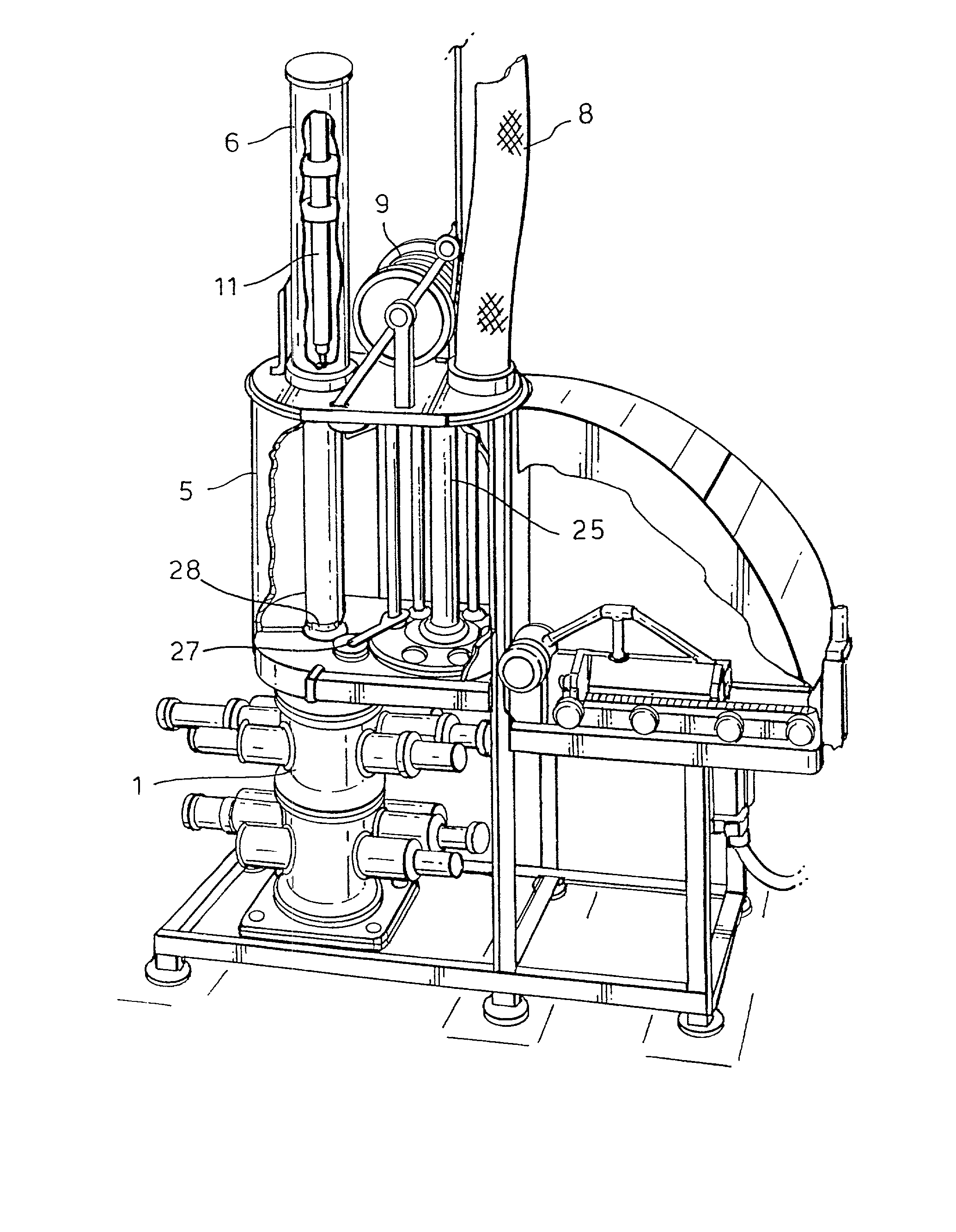
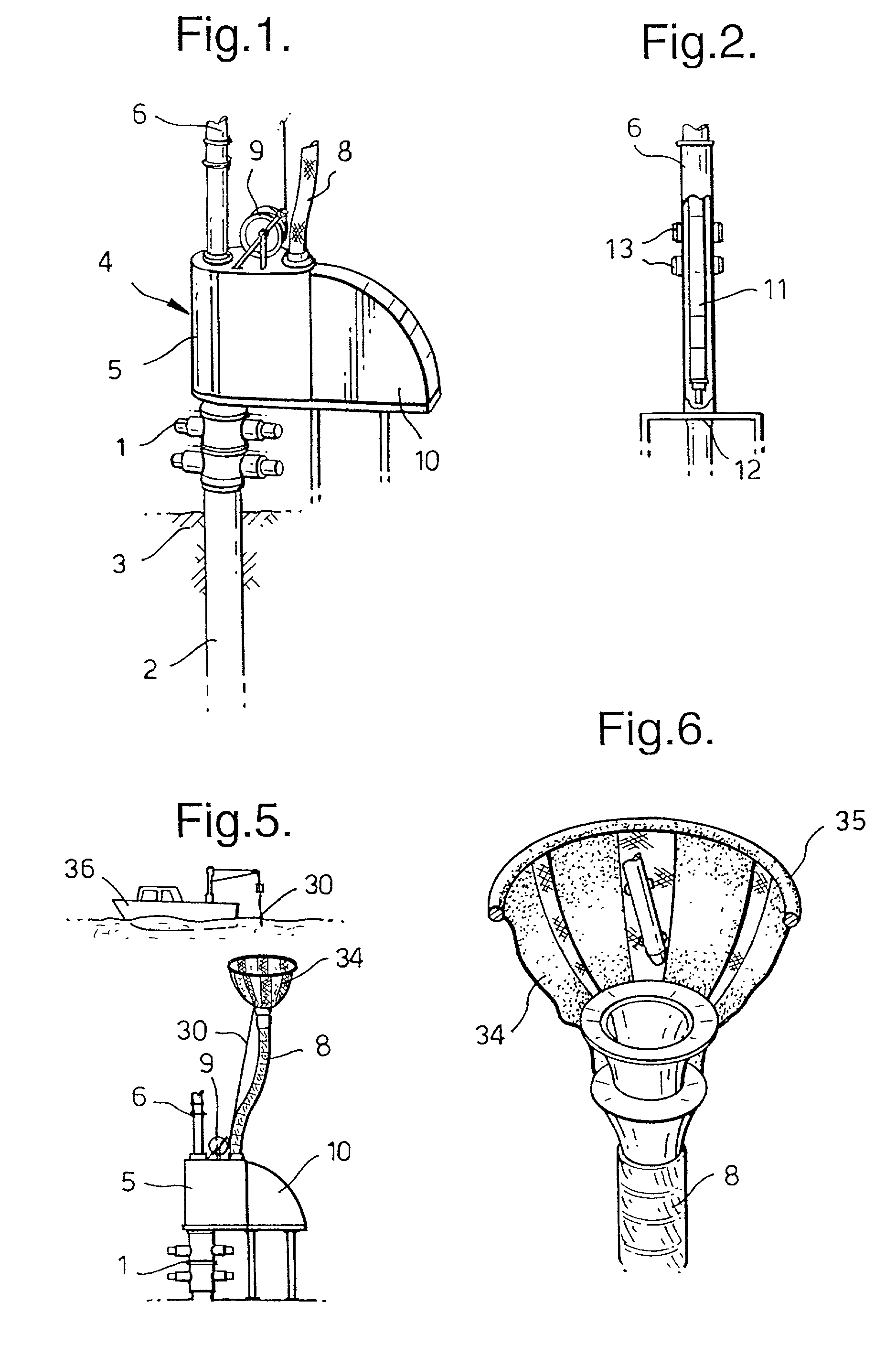
[0034] Referring now to FIG. 1 there is shown a wellhead 1 of an oil and / or gas well 2, which penetrates into an underground formation 3.

[0035] On the wellhead 1 an equipment storage and handling unit 4 is mounted, which comprises a carousel housing 5 on which a shuttle device launch conduit 6, a flexible equipment dropping ducting 8, a winch 9 for the ducting 8 and an underwater vehicle (AUV) docking and equipment transfer unit 10 are mounted.

[0036] FIG. 2 shows the shuttle device launch conduit 6 in which a shuttle device 11 is located.

[0037] The shuttle device 11 rests on a gate 12 which is mounted on top of the carousel housing 5 and electrical power is being supplied to the batteries of the shuttle device 11 via a pair of inductive connectors 13.

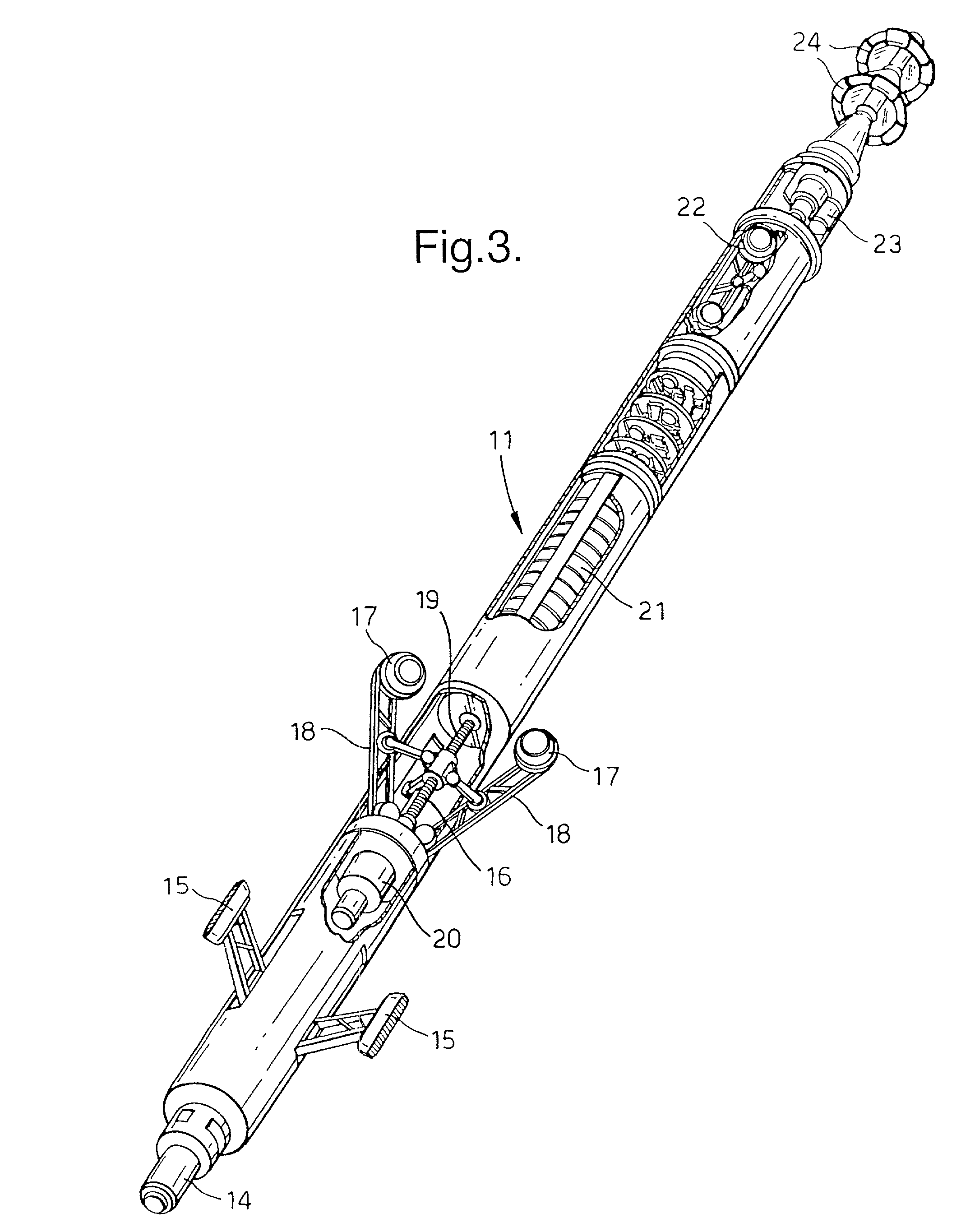
[0038] FIG. 3 shows in detail the shuttle device 11 of FIG. 2.

[0039] The front part of the shuttle device 11 comprises an equipment module connector 14, a set of three articulated bracing feet 15 (two of which are shown), an expandable ...


PUM


Abstract

A method and system are disclosed for moving equipment into and through a conduit that is preferably an oil and / or gas production well, wherein use is made of an uphole equipment storage and handling unit via which equipment modules can be moved into a launch conduit and connected to a shuttle device which is able to locomote itself as a wireless tractor via the launch conduit into and from the underlying conduit.

Description

[0001] The invention relates to a method and system for transporting equipment through an underground well.BACKGROUND TO THE INVENTION[0002] In underground oil and / or gas production wells transportation of equipment generally requires complex procedures and transportation systems. Currently available systems include slick-wireline systems, coiled tubing, electric downhole tractors and through flow line (TFL) systems. TFL systems employ TFL pistons that are pumped up and down through a production tubing, which requires the installation of parallel production tubings which are interconnected downhole so that fluid can be circulated in opposite directions. The use of parallel production tubings is expensive and reduces the amount of oil and / or gas that can be produced via the well.[0003] The other available systems require complex equipment which is linked to coiled tubing injectors, or power cable or wireline drums from which tubings, power cables and / or wirelines, that may be up to a...

Claims


Application Information

Patent Timeline
Patent Type & Authority Applications(United States)
IPC IPC(8): E21B4/18E21B19/00E21B19/14E21B23/00E21B23/10E21B33/076
CPCE21B4/18E21B19/002E21B19/143E21B19/146E21B23/00E21B23/10E21B33/076E21B2023/008E21B23/001
Inventor SCHEMPF, HAGENKIMMINAU, STEVE JOHNDEN BOER, JOHANNIS JOSEPHUSSTEWART, JOHN FOREMANBIJLEVELD, AARNOUD FREDERIC
Owner SHELL OIL CO
Why Eureka
Try Eureka