Optical pre-amplifier apparatus and method for receiver performing gain control according to los declaration

a preamplifier and receiver technology, applied in the field of optical communication receivers, can solve the problems of increasing the ber (bit error rate) and the inability to increase the ber, and achieve the effect of preventing an increase in the ber and reducing the amount of pump 40 power level changes

Inactive Publication Date: 2003-02-13
CIENA
View PDF0 Cites 33 Cited by
  • Summary
  • Abstract
  • Description
  • Claims
  • Application Information

AI Technical Summary

Benefits of technology

0088] The use of such windows is particularly advantageous in the optical signaling and reception environment. Adjusting the pump 40 power excessively may introduce noise and cause the BER (bit error rate) to rise. Any increase in the BER is unacceptable as the specifications for BER are extremely demanding (on the order of 10.sup.-15 bit errors per second being an acceptable BER). The use of windows reduces the amount of pump 40 power level changes and possible race round conditions due to minor variations in power and thereby prevents an increase in the BER.
0089] The windowing concept has other advantages for companies deplo

Problems solved by technology

Adjusting the pump 40 power excessively may introduce noise and cause the BER (bit error rate) to rise.
Any increase in the BER is unacce

Method used


Image

  • Optical pre-amplifier apparatus and method for receiver performing gain control according to los declaration
  • Optical pre-amplifier apparatus and method for receiver performing gain control according to los declaration
  • Optical pre-amplifier apparatus and method for receiver performing gain control according to los declaration

Examples


Embodiment Construction

[0041] The following detailed description of the invention refers to the accompanying drawings. The same reference numbers in different drawings identify the same or similar elements. Also, the following detailed description does not limit the invention. Instead, the scope of the invention is defined by the appended claims and equivalents thereof.

[0042] The expressions "optically communicates" and "optically coupled" as used herein refer to any connection, coupling, link or the like by which optical signals carried by one optical system element are imparted to the "communicating" or "coupled" element. Such "optically communicating" or "optically coupled" devices are not necessarily directly connected to one another and may be separated by intermediate optical components or devices.

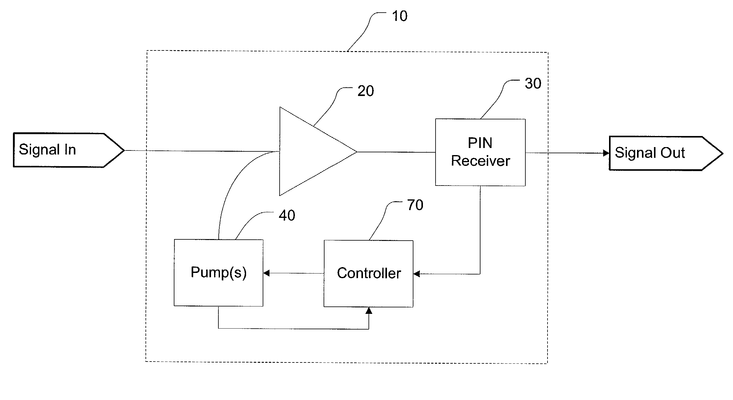
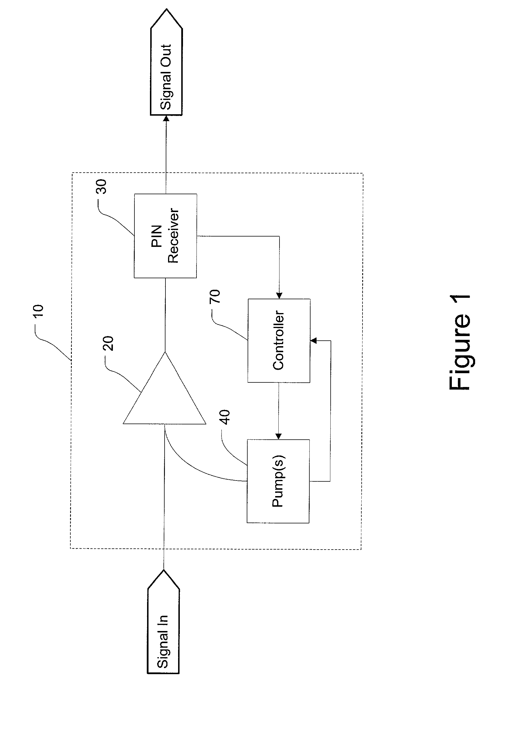
[0043] FIG. 1 illustrates a construction of the inventive pre-amplified receiver node 10 which will also be referred to herein as a receiver node 10.

[0044] The receiver node 10 includes an optical amplifie...


PUM


Abstract

A receiver node includes an optical amplifier optically coupled to the input of a receiving device such as a PIN photodiode. A controller inputs received power level values from the receiver to perform gain control. The input signal of an optical receiving device, is pre-amplified by an optical amplifier such that the amplified signal is within a dynamic range of the receiving device. Upon the occurrence of a LOS (loss of signal) event, the controller sets the gain to a Home Gain value. Thus, when the signal is reestablished, a strong signal will not be over amplified and damage the receiver. Gain control is reestablished when the LOS event is over. Various methods are used to declare LOS including comparing the received power level or commanded pump power against a threshold. The LOS declaration may also be received from an external device or service channel.

Description

[0001] 1. Field of Invention[0002] The invention generally relates to optical communication receivers. The invention more particularly relates to optically pre-amplified receiver nodes.[0003] 2. Description of Related Art[0004] In conventional long-haul optical communications applications, the loss between the laser transmitter and the receiver is typically fixed or otherwise substantially invariant. Therefore, a gain block with fixed optical gain serves the purpose of ensuring that the receiver will receive a signal within the receiver's dynamic range.[0005] In some applications such as metropolitan optical ring networks, however, the loss between the laser transmitter and the receiver often changes due to changes in the span loss or due to channel upgrades. During channel upgrades, extra OADMs (optical add drop multiplexers) are added into the optical path of existing channels, therefore the loss between the transmitter and the receiver changes.[0006] Furthermore, a complete fiber...

Claims


Application Information

Patent Timeline
IPC IPC(8): H01S3/067H01S3/10H01S3/131H04B10/08H04B10/17
CPCH01S3/06754H04B10/077H01S3/1301H04B10/2931H04B10/07955H01S3/13013H01S3/1001
Inventor CORNELIUS, STEVENCORWIN, ROBERTMILLER, DONALD J.BROWNLEE, JOHNDASIKA, PRASAD
Owner CIENA
Why Eureka
Try Eureka