
Mode sensitive filter and optical transmitter/receiver

Inactive Publication Date: 2003-02-13
PHOTONIXNET
View PDF2 Cites 4 Cited by
  • Summary
  • Abstract
  • Description
  • Claims
  • Application Information

AI Technical Summary

Benefits of technology

[0009] This object and others will be achieved by an optical transmitter / receiver according to the present invention comprising an optical fiber or an optical waveguide having a single transmission mode in a long wavelength range (1.2-1.7 .mu.m) and a mode sensitive filter connected to an optical fiber or an optical waveguide having a single transmission mode in a short wavelengthBACKGROUND OF THE INVENTION range (0.6-1.0 .mu.m). With this construction, the optical transmitter / receiver can remove high-order modes generated when transmitting light having a short wavelength along optical fibers having a single transmission mode in the long wavelength range. Accordingly, it is possible to perform broadband transmissions using a short wavelength optical transmitter / receiver comprising inexpensive light-emitting and light-receiving devices. A particular feature of the present invention is its selection of semiconductor lasers formed of inexpensive GaAs-AlGaAs with a wavelength of 0.75-0.88 .mu.m and the most common single-mode optical fibers used in optical communications with an operating wavelength of 1.30-1.65 .mu.m. With this construction, it is possible to anticipate the present invention being applied to a wide-range of applications at the lowest cost possible.

Problems solved by technology

Multiple transmission modes give rise to problems of differential mode delay (DMD) caused by each transmission mode traveling in a different optical path.
DMD is known to greatly degrade the data transfer rate.
Accordingly, high-speed optical communications are not possible when multiple transmission modes are generated in the fiber.
On the other hand, InP semiconductor lasers are limited in applications to optical communications and, therefore, require more expensive materials and manufacturing equipment.
Photodiodes supporting longer wavelengths (1.2-1.70 .mu.m) have been more expensive to manufacture because they require the use of InP material.
However, a large amount of single-mode fibers (optical fibers having a single transmission mode in the above long wavelength region) are already in existence, presenting difficulties in laying new optical fibers having different core diameters.

Method used


Image

  • Mode sensitive filter and optical transmitter/receiver
  • Mode sensitive filter and optical transmitter/receiver
  • Mode sensitive filter and optical transmitter/receiver

Examples


first embodiment

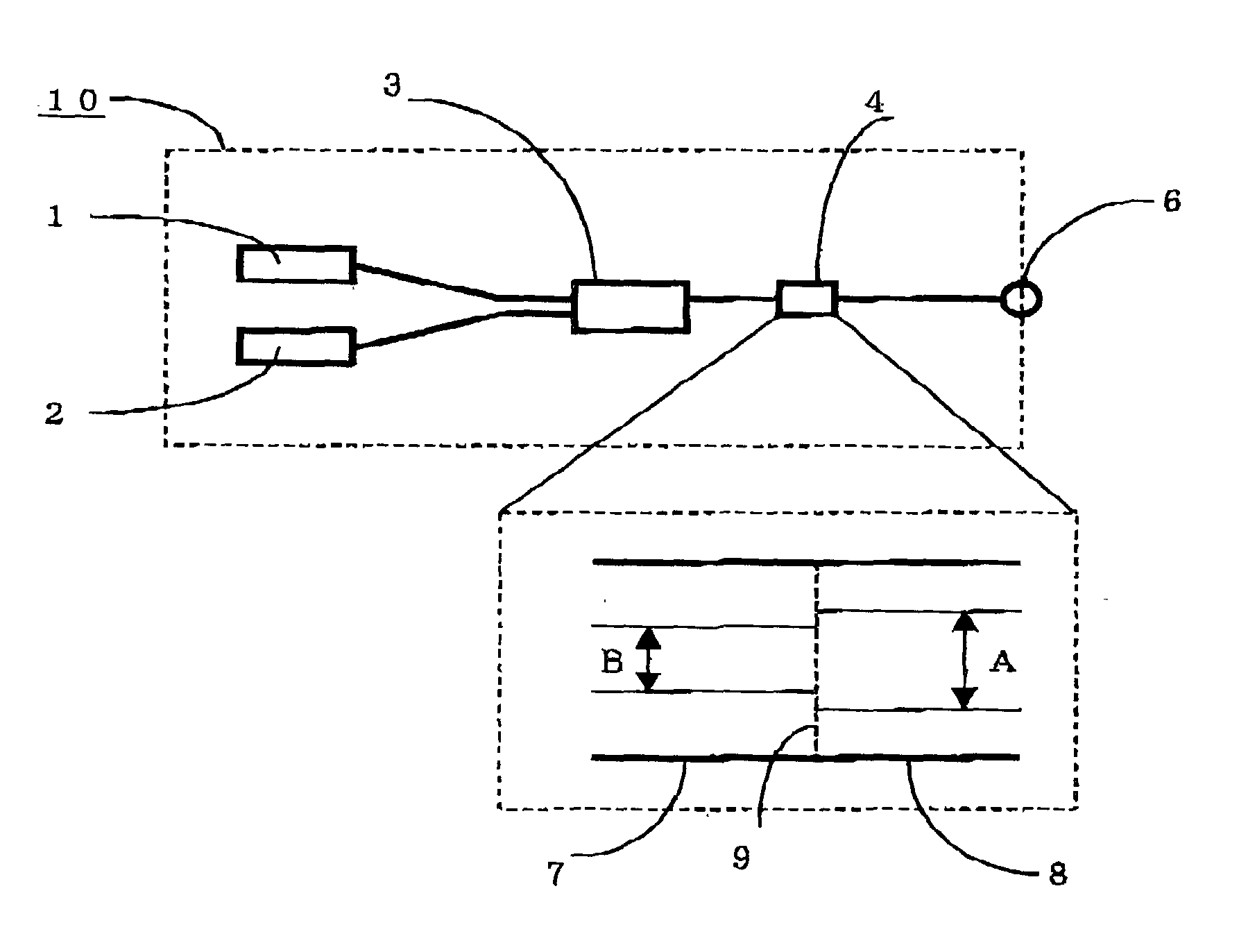
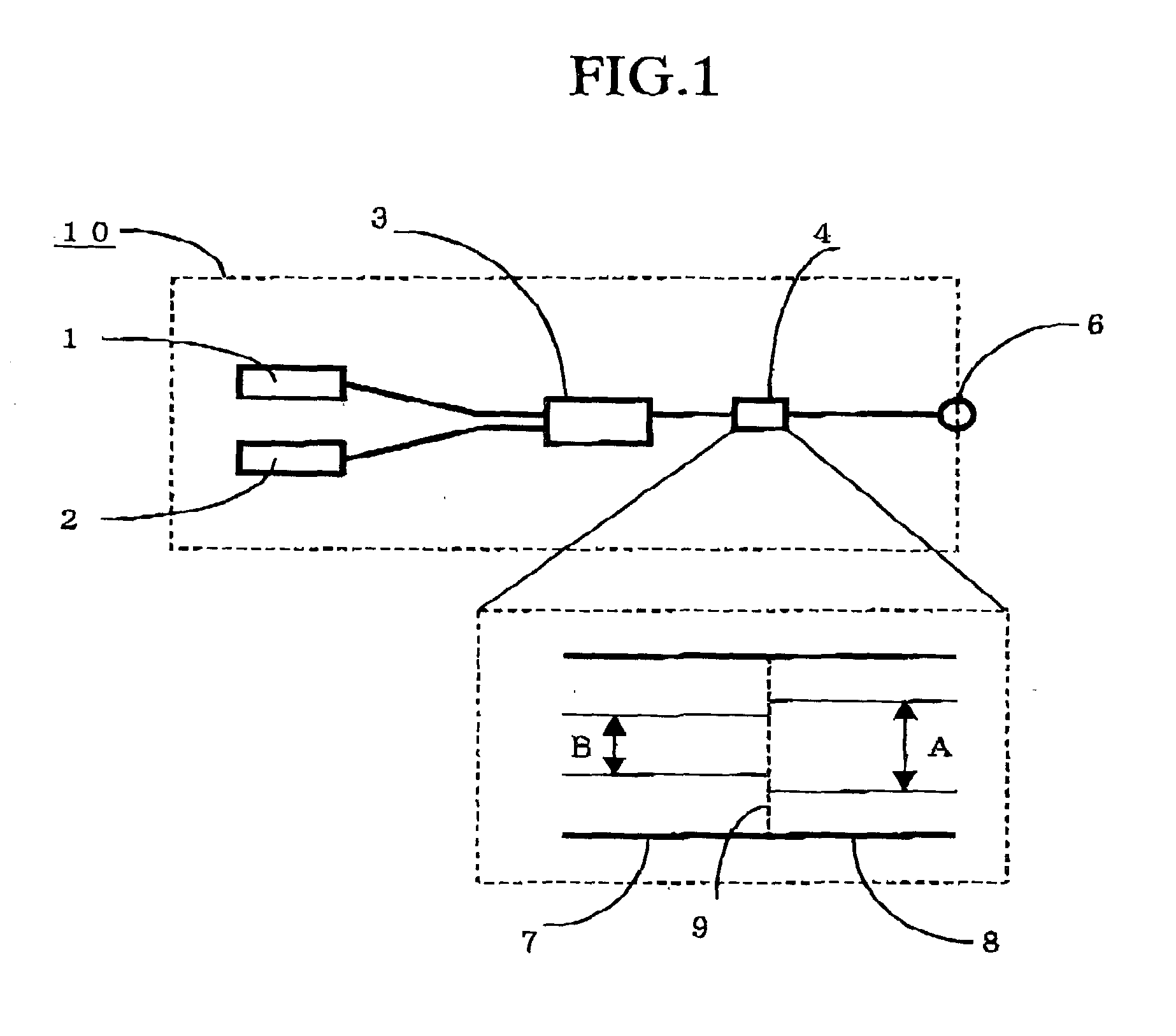
[0017] FIG. 1 shows the basis construction of a optical transmitter / receiver according to the present invention. An optical transmitter / receiver 10 of the present invention comprises a semiconductor laser 1, a photodiode 2, a WDM (wavelength division multiplexing) optical fiber coupler 3, and a mode sensitive filter 4. The semiconductor laser 1 employs an AlGaAs laser grown on a GaAs substrate. The photodiode 2 is a light-receiving element that comprises a Si-Pin photodiode grown on a Si substrate. The mode sensitive filter 4 is configured such that an optical fiber 7 having a core diameters B of 6 .mu.m and an optical fiber 8 having a core diameter A of 10 .mu.m are coaxially fusion spliced together at an interface 9. Light having a wavelength 0.78 .mu.m (or 0.85 .mu.m) travels in a single mode on the optical fiber 7 end of the mode sensitive filter 4. This short wavelength from the optical fiber 7 end is coupled with the lowest order mode on the optical fiber 8 end.

[0018] While li...

second embodiment

[0028] [SECOND EMBODIMENT]

[0029] FIG. 3 is a plan view showing the construction of an optical transmitter / receiver according to a second embodiment of the present invention. The optical transmitter / receiver of the present embodiment is configured of a WDM coupler 14 disposed on a planar optical waveguide substrate 11. A mode sensitive filter 13 is formed at the junction between the planar optical waveguide substrate 11 and an optical fiber 12. The semiconductor laser 1 and photodiode 2 are the same as those in the first embodiment shown in FIG. 1.

[0030] The mode sensitive filter 13 of the present embodiment is configured such that a waveguide 15 formed on the planar optical waveguide substrate 11 has a small cross-sectional area in order to generate a single mode on the short wavelength end. Since the optical fiber 12 is a normal single-mode optical fiber (an optical fiber having a single transmission mode of a long wavelength), a plurality of transmission modes exists in the optica...


PUM


Abstract

An optical transmitter / receiver provided with a mode sensitive filter configured by joining an optical fiber or optical waveguide having a single transmission mode at a long wavelength (1.2-1.7 mum) and an optical fiber or optical waveguide having a single transmission mode at a short wavelength (0.6-1.0 mum). With this construction, the optical transmitter / receiver can remove high-order modes generated when transmitting light having a short wavelength along optical fibers having a single transmission mode in the long wavelength range. Accordingly, it is possible to perform broadband transmissions using an inexpensive, short wavelength optical transmitter / receiver.

Description

[0001] The present invention relates to an optical transmitter and receiver and a mode sensitive filter therefor.[0002] Optical fibers known as single-mode fibers are widely used in the art. In its broad sense, a single-mode fiber is the generic term for an optical fiber that supports only one transmission mode at any one time. More specifically, a single-mode fiber is an optical fiber supporting a single transmission mode at a wavelength of 1.2 .mu.m or greater. A single-mode fiber of the latter definition normally has a core diameter of about 10 .mu.m.[0003] It is well known in the art that a plurality of transmission modes will be generated when attempting to transmit light with a wavelength of 0.78 .mu.m, for example, along this type of single-mode fiber. FIG. 4 is an explanatory diagram showing this process. In a fiber with a core diameter Da of 10 .mu.m, light having a wavelength .lambda.a of 1.3 .mu.m propagates in a single mode, as shown in FIG. 4(a). However, when transmitt...

Claims


Application Information

Patent Timeline
IPC IPC(8): G02B6/30G02B6/00G02B6/14G02B6/34G02B6/42H04B10/25H04B10/291H04B10/40H04B10/50H04B10/60
CPCG02B6/14G02B6/30G02B6/4246
Inventor OTA, TAKESHI
Owner PHOTONIXNET
Learn More