Catalytic testing device and method for its use in material testing

a testing device and material technology, applied in the direction of catalyst activation/preparation, flow control, temperatue control, etc., can solve the problems of not being able to achieve any kind of control or measure over the streams circulating through each catalyst, and not being able to achieve any kind of control or measure over the different temperatures, etc., to achieve quick and accurate decision

Inactive Publication Date: 2003-02-27
CONSEJO SUPERIOR DE INVESTIGACIONES CIENTIFICAS (CSIC) +1
View PDF12 Cites 28 Cited by
  • Summary
  • Abstract
  • Description
  • Claims
  • Application Information

AI Technical Summary

Benefits of technology

0035] The reaction block can in turn comprise a plurality of bodies thermally insulated from each other, with each body presenting an individual heating system and an individual temperature regulation system. This allows different sections or bodies at different temperatures to be had in the reaction block, if wished, thus making it possible to have a series of individual reactors at different temperatures.
0036] Also, the reaction block can be designed in such a way that it is extractable, thereby making it possible for that block to be exchanged for another reaction block and / or other processes to be conducted on the materials housed inside this reaction block in another installation or in a different device.
0037] The device of the present invention permits catalytic tests to be conducted with a wide range of reagents or mixtures (especially suited for catalytic experiments in oil refining, petrochemistry and chemistry, where the reactions can include mixtures of hydrocarbons coming from a real refinery stream), which can be in both the gaseous and liquid phase, under reaction conditions (temperature, pressure, contact time, hydrodynamic flow), comparable to those occurring in industrial processes. The possibility can be highlighted of working at pressures of up to 150 atmospheres thanks to the novel system of dynamic pressure regulation that has been developed. These aspects are considered to be highly relevant since they permit a quick and accurate decision to be taken on the suitability of a material for the catalysis of a chemical process at the industrial scale.
0038] The amount of catalyst needed for carrying out a test can vary from 20 milligrams to 10 grams. In this way, it is not necessary to have large quantities of material available as usually occurs in conventional catalytic testing systems.

Problems solved by technology

Nevertheless, the search for a specific catalyst is a costly task requiring the preparation of a large number of formulations, with their consequent testing in a reaction system.
This entails very extensive periods of time until a suitable catalyst is successfully developed.
The application for German patent DE-A-19809477 provides a reactor with different cavities where different catalysts are housed, permitting simultaneous testing but without achieving any kind of control or measure over the streams circulating through each catalyst, nor over the different temperatures.
Moreover, the system described in that German patent application does not provide anything regarding the feed system for the products, pressure regulation, sample taking or subsequent analysis, all of them are fundamental aspects when it comes to having a suitable reaction system.
The main limitations of this system when it comes to achieving realistic reaction conditions are: (i) absence of automatic and dynamic pressure control, which would permit regulation of the pressure in all individual reactors and its possible variation during the course of the reaction tests; in addition to the fact that it is not possible to use them at high pressure; (ii) impossibility of varying the chemical composition of the feed currents for the different reaction compartments; (iii) absence of a prior conditioning stage for each individual feed current.
Nevertheless, in no way do these inventions guarantee acceptable conditions for catalytic testing according to the criteria stated above, yet on the contrary our reaction system does indeed guarantee this.

Method used


Image

  • Catalytic testing device and method for its use in material testing
  • Catalytic testing device and method for its use in material testing
  • Catalytic testing device and method for its use in material testing

Examples


Embodiment Construction

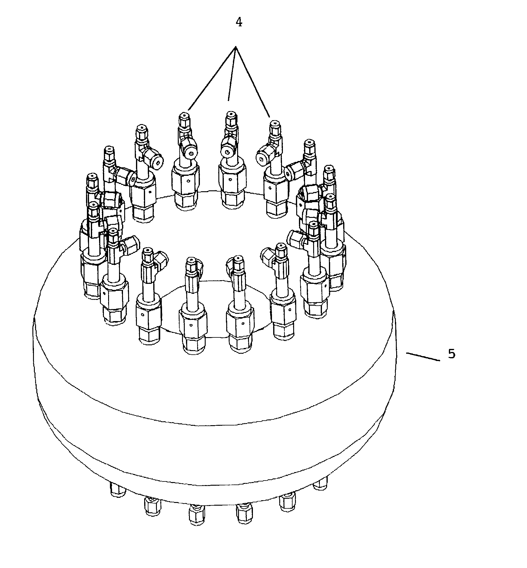
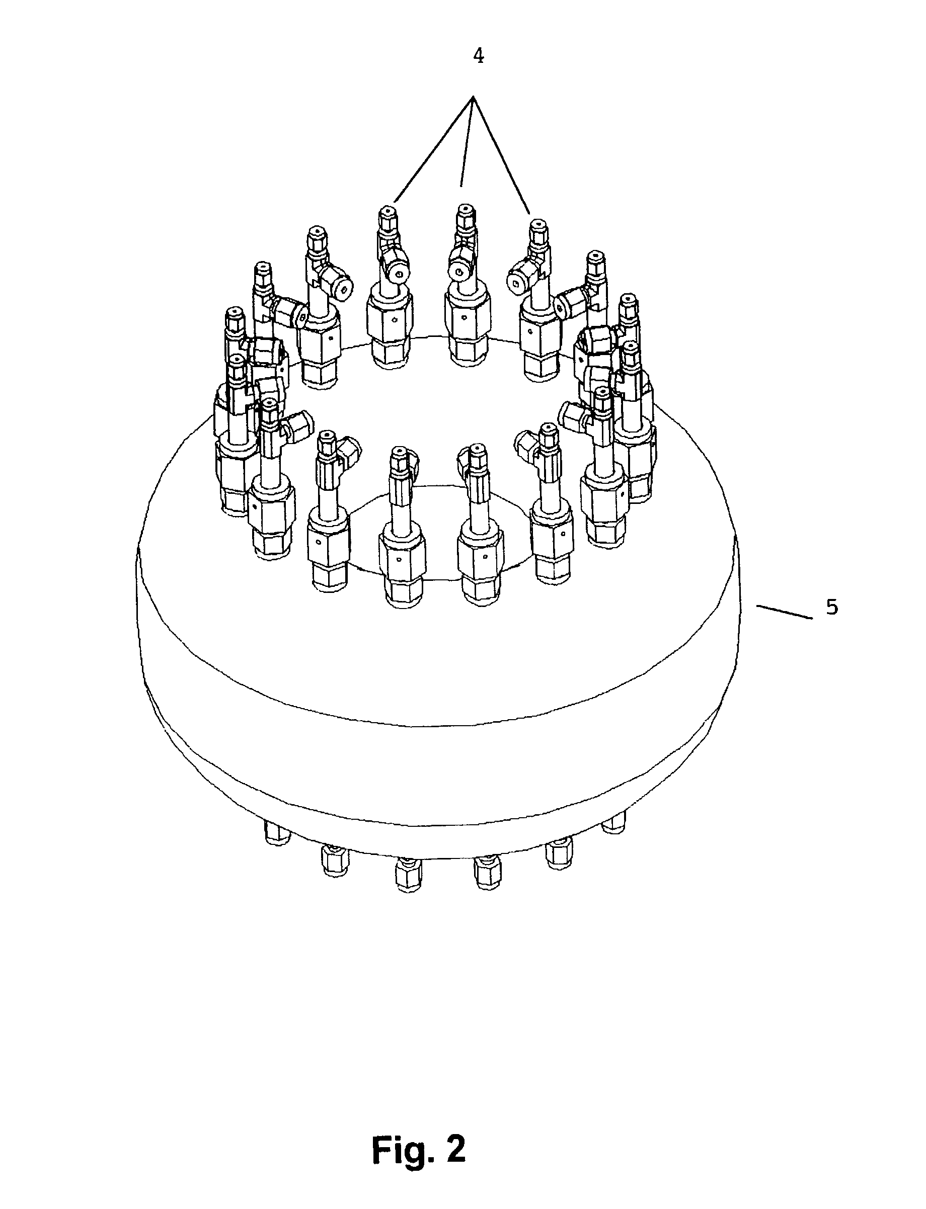
[0015] The objects and objectives specified above are achieved by means of an automatic device for catalytic testing which includes

[0016] at least one reaction block consisting of an array of reaction chambers capable of housing solid materials inside and with each chamber having a fluid input, and an output connected to an outgoing fluid duct that links up with analysis means (such as for example analysis means selected from among gas chromatography systems, mass spectrometry systems, visible spectrometry systems, ultraviolet spectrometry systems, infrared spectrometry systems and ultra-fast gas chromatography systems consisting of a set of capillary tubes arranged in columns selected from among columns of multiple capillaries in parallel and multicapillary columns, for the separation of different chemical compounds present in the outgoing fluid from each reaction chamber),

[0017] fluid feed means (such as for example a mass stream regulating system based on changes in temperature d...


PUM

PropertyMeasurementUnit
temperatureaaaaaaaaaa

Abstract

A catalytic testing device comprising a reaction block comprising a set of reaction chambers, each chamber comprising a fluid inlet and outlet connected to an outgoing fluid duct connected to analysis means, fluid feed means capable of performing regulated dosing of flows of the fluid at the required pressure independently in each of the reaction chambers, automatic and dynamic pressure control means, capable of performing pressure regulation in each reaction chamber, which comprise a non-return valve in the outgoing fluid duct between the outlets of the reaction chambers and a common regulating tank that receives the outgoing fluid from the chambers, a pressure sensor provided in a first outlet duct and an automatic needle valve provided in a second outlet duct from the tank.

Description

[0001] This invention belongs to the technical field of analysis systems for chemicals and particularly to the sector of catalytic testing systems.STATE OF THE ART PRIOR TO THE INVENTION[0002] Advances in the chemical industry have largely been due to the development of new catalytic processes that make it possible to carry out production under especially adequate conditions of a range of chemicals such as medicines, polymers, fuels, etc. The key to the development of a catalytic process is, first of all, the availability of a catalyst that permits the reaction or set of reactions to take place under certain more interesting conditions from the point of view of economy, safety and versatility of the process. Nevertheless, the search for a specific catalyst is a costly task requiring the preparation of a large number of formulations, with their consequent testing in a reaction system. This entails very extensive periods of time until a suitable catalyst is successfully developed. The...

Claims


Application Information

Patent Timeline
Patent Type & Authority Applications(United States)
IPC IPC(8): B01J19/00B01J37/00B01L3/00B01L7/00C40B30/08C40B40/18G01N30/02G01N30/46G01N31/10G01N33/00G01N35/08
CPCB01J19/0046Y10T436/21B01J2219/00313B01J2219/00389B01J2219/00477B01J2219/00495B01J2219/00585B01J2219/00601B01J2219/00686B01J2219/00698B01J2219/00704B01J2219/00716B01J2219/00745B01J2219/00747B01L3/502B01L7/00B01L2400/0487B01L2400/0622C40B30/08C40B40/18G01N31/10G01N35/08Y10T436/117497Y10T436/216Y10T436/214Y10T436/24B01J2219/00286
Inventor CANOS, AVELINO CORMASERRA ALFARO, JOSE MANUELFENOLLOSA, JUAN HERNANDEZ
Owner CONSEJO SUPERIOR DE INVESTIGACIONES CIENTIFICAS (CSIC)
Why Eureka
Try Eureka