Dual band framing reconnaissance camera

a reconnaissance camera and band framing technology, applied in the field of aerial reconnaissance photography and camera systems, can solve the problems of distorted images, and inability to achieve and the scanning system inherently is prone to creating geometrically and geospatially distorted images

Inactive Publication Date: 2003-03-27
THE BF GOODRICH CO
View PDF3 Cites 9 Cited by
  • Summary
  • Abstract
  • Description
  • Claims
  • Application Information

AI Technical Summary

Benefits of technology

[0021] The servo-mechanical subsystem also includes a second motor system coupled to the objective optical subassembly. In the illustrated embodiment, the objective optical subassembly comprises a catoptric Cassegrain optical system. The second motor system rotates the Cassegrain optical system about a second axis in the direction of forward motion of the reconnaissance vehicle to compensate for the forward motion of the aerial reconnaissance vehicle. The action of the first motor assembly to rotate the entire camera housing about the roll axis occurs at the same time (i.e., simultaneously with) the action of the second motor system to rotate the Cassegrain optical system in the line of flight to accomplish forward motion compensation. The net effect of the action of the Cassegrain motor system and the roll motion compensation system is that the image of the scene of interest is essentially frozen relative to the focal plane of the image recording media while the media obtain the frames of imagery, allowing high resolution images of the scene in two different bands of the spectrum to be obtained simultaneously. Furthermore, the rotation of the image scene caused by the roll motion of the objective subassembly is simultaneously detrotated by the roll motion of the rest of the camera, in view of the fact that the entire camera assembly is rolled as a unit, thereby eliminating the need for a separate derotation mechanism such as a pechan prism. Other types of optical arrangements for the objective optical subassembly are possible, but are less preferred. The operation of the camera with the different type of objective subassembly is the same.
[0024] As noted above, the present invention required the solution to several difficult technical challenges, including optical, servo-mechanical and operational difficulties. For an electro-optical framing LOROP camera to operate in at least two discrete bands of the electromagnetic spectrum at the same time, the optical challenge is to focus panchromatic energy (e.g. visible through IR) on a focal plane detector with (1) good image quality and satisfactory modulation transfer function, (2) while baffling stray energy, (3) meeting space constraints, and (4) enabling the use of a relatively large two-dimensional area array as a focal plane detector to get an adequate field of view and resolution. In accordance with one aspect of the invention, these optical challenges were solved by a unique catoptric Cassegrain objective optical subassembly incorporating an azimuth mirror and utilizing separate field optics for each band of the spectrum, described in more detail herein.
[0026] This servo-mechanical situation required a unique inventive solution, described in detail herein. The solution, as provided in one aspect of the present invention, was to (1) rotate the entire camera (including the entire optical system and the image recording media) smoothly in a continuous fashion about an axis parallel to the aircraft roll axis, similar to the pan-type movement, but without the starts and stops used in a traditional step-frame camera system, and (2) operating the camera as a framing camera while the camera undergoes the smooth rotation. Frames of imagery are thus taken while the camera smoothly rotates about the roll axis at a constant angular velocity. In addition to this novel "roll-framing" technique, the present invention also electronically compensates for, i.e., stops, the image motion due to roll while the camera is scanning in a smooth motion. Meanwhile, a novel forward motion compensation technique is performed by the Cassegrain optical subassembly to cancel out image motion effects due to the forward motion of the aircraft. The result enables exposures of the image recording media to the scene while compensating for roll and forward motion, enabling high-resolution images to be obtained.
[0027] The present invention thus solves the difficult optical, servo-mechanical and operational problems and provides a dual band framing, electro-optical LOROP camera that delivers a performance and technical capability that has never before been achieved. In particular, it provides a system by which high-resolution frames of imagery in two different portions of the electromagnetic spectrum can be generated simultaneously. The inventive camera can be used in a quasi-stepping mode, in which overlapping frames of imagery are obtained across the line of flight. It can also be used in a spot mode, in which the camera is oriented in a particular direction to take an image of a target expected to be in the field of view.

Problems solved by technology

These operational issues were hostage to the technological limitations of the day.
The disadvantage is that each line of exposed imagery was taken from a different perspective, hence the scanning system inherently was prone to creating geometrically and geo-spatially distorted images.
Again, the disadvantage of this method was that imagery was obtained from a different perspective as the aircraft moved, resulting in geometrically and geospatially distorted images.
The disadvantage of step framing cameras was that the stepping action was very difficult to accomplish with the whole camera, therefore it had to be broken into a scan head that performed the stepping and an image de-rotation mechanism, both of which were tied together by a synchronized drive system.
However, the implementation of such a camera presents a number of difficulties and technical challenges beyond those posed for prior art systems.
The standard solution of stepping the entire LOROP camera system or even a large scan mirror assembly at the operational frame rate are not acceptable alternatives for large LOROP cameras, an in particular large dual band systems.
The diversity of these applications posed a power and stability problem that prevents application of prior art solutions.
The task of stepping a 400 lb. camera mass two to four times a second creates tremendous inertial loads as well as power spikes that would be unacceptable.
Even the inertia and associated settling times of a stepped scan head assembly pose problems in some applications.

Method used


Image

  • Dual band framing reconnaissance camera
  • Dual band framing reconnaissance camera
  • Dual band framing reconnaissance camera

Examples


Embodiment Construction

[0056] Overview and Method of Operation:

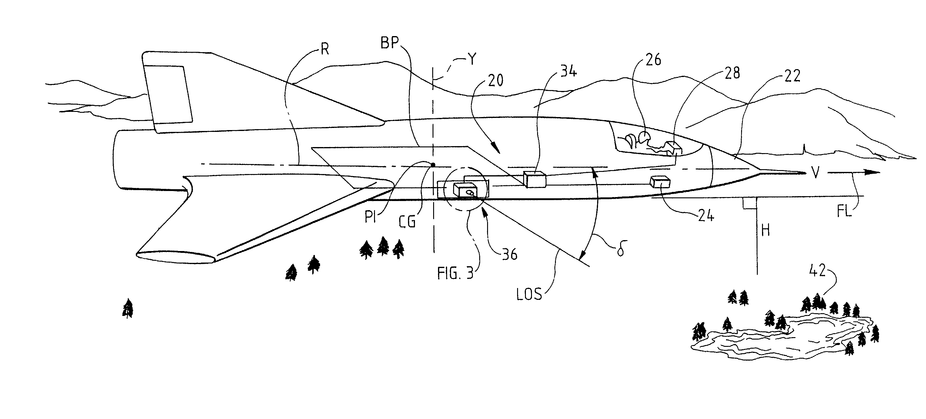
[0057] Referring now to FIG. 1, an aerial reconnaissance camera system 20 in accordance with a preferred embodiment of the invention is shown installed in a reconnaissance aircraft 22 flying over a terrain of interest 42 at an altitude H and with forward velocity V, moving in a direction of flight FL. The aerial reconnaissance camera system 20 includes a camera 36, shown in greater detail in FIGS. 2A-2C and 3-5, a camera control computer 34 and associated electronics described in further detail in FIGS. 17 and 19. The camera control computer receives certain navigational information from the aircraft avionics system 24, including current aircraft velocity and height data. Additional camera system inputs may come from a console 28 in the cockpit, such as start and stop commands or camera depression (roll angle) settings.

[0058] The aircraft body defines a roll axis R, a pitch axis PI and a yaw axis Y passing through the center of gravity CG of t...


PUM


Abstract

A framing aerial reconnaissance camera is described which has a catoptric Cassegrain optical system forming an objective lens that directs radiation to a spectrum-dividing prism. The prism directs radiation in the visible portion of the electromagnetic spectrum into a first optical path having a two-dimensional image-recording medium, such as a charge-coupled device. Radiation in the infrared (IR) band of the spectrum is directed to a second optical path, which has a two-dimensional IR-sensitive image-recording medium, such as an electro-optical IR imaging array. The entire camera is rotated about the aircraft roll axis in a continuous fashion to generate frames of imagery providing panoramic coverage of the scene across the line of flight. While the camera is being rotated about the roll axis, the arrays are exposed to the scene repeatedly to al generate a series of two-dimensional frames of imagery. Forward motion compensation is accomplished by rotation of the Cassegrain optical system in the direction of flight. Image motion due to the camera roll is canceled out in the array by moving pixel information through the arrays as the same rate as the image rotation due to roll. The combination of roll motion compensation and forward motion compensation freezes the image relative to the image recording media, allowing high resolution images to be obtained of the terrain of interest in two different bands of the electromagnetic spectrum simultaneously.

Description

[0001] This application is related to the following patent applications filed on the same date as this application, the contents of each of which is incorporated by reference herein:[0002] Andrew J. Partynski et al., METHOD FOR FRAMING RECONNAISSANCE WITH ROLL MOTION COMPENSATION, Ser. No. ______;[0003] Stephen R. Beran et al., METHOD OF FORWARD MOTION COMPENSATION IN AN AERIAL RECONNAISSANCE CAMERA, Ser. No. ______;[0004] Stephen R. Beran et al., CASSEGRAIN OPTICAL SYSTEM FOR FRAMING AERIAL RECONNAISSANCE CAMERA, Ser. No. ______;[0005] A. Field of the Invention[0006] This invention relates generally to the field of aerial reconnaissance photography and camera systems used for such photography. More particularly, in a principal aspect the invention relates to a reconnaissance camera that generates frames of imagery of terrain in different portions or bands of the electromagnetic spectrum simultaneously.[0007] The invention also relates to a novel method by which a camera compensates...

Claims


Application Information

Patent Timeline
Patent Type & Authority Applications(United States)
IPC IPC(8): G01C11/02G02B7/18G02B17/08
CPCG01C11/025G02B7/18G02B17/0808G02B17/0852G02B17/0896H04N5/2251H04N23/50
Inventor PARTYNSKI, ANDREW J.BERAN, STEPHEN R.BAKER, ALLIE M.JONES, JOHNWYATT, STEPHAN
Owner THE BF GOODRICH CO
Why Eureka
Try Eureka