Method and apparatus for controlling variable air volume supply fans in heating, ventilating, and air-conditioning systems

a technology of variable air volume and supply fans, which is applied in the direction of vehicle heating/cooling devices, railway components, machines/engines, etc., can solve the problems of increasing the cost of the hvac system, inefficient at part-load conditions, and sensitive to communication failures, so as to improve energy efficiency, improve energy efficiency, and improve energy efficiency

Inactive Publication Date: 2003-04-03
VIGILENT CORP
View PDF5 Cites 67 Cited by
  • Summary
  • Abstract
  • Description
  • Claims
  • Application Information

AI Technical Summary

Benefits of technology

0018] Accordingly, a primary object of the present invention is to provide a control strategy for supply fans of variable-air-volume heating, ventilating, and air-conditioning systems that can improve the energy efficiency at part-load conditions without requiring that the positions of terminal dampers be measured.
0019] Another object of the present invention is provide a control strategy for supply fans of variable-air-volume heating, ventilating, and air-conditioning systems that can improve the energy efficiency at part-load conditions without being sensitive to a communication system failure.
0020] Another object of the present invention is provide a control strategy for supply fans of variable-air-volume heating, ventilating, and air-conditioning systems that can improve the energy efficiency at part-load conditions without being sensitive to a failure of a terminal unit.
0021] Another object of the present invention is provide a control strategy for supply fans of variable-air-volume heating, ventilating, and air-conditioning systems that can improve the energy efficiency at part-load conditions without being sensitive to a design flaw in which one or more terminal units is undersized.
0022] Another object of the present invention is provide a control strategy for supply fans of variable-air-volume heating, ventilating, and air-conditioning systems that can improve the energy efficiency at part-load conditions and is easy to tune.

Problems solved by technology

A problem with this strategy is that it is inefficient at part-load conditions, when the supply flow rate is significantly lower than a design flow rate, which is the flow rate at which the system should operate when the fan is running at full speed.
One problem with resetting static pressure based on the position of the most-open terminal damper is that it requires that the control system be able to measure the position of every terminal damper.
Requiring terminal damper position measurement adds cost to the HVAC system.
Another problem with resetting static pressure based on the position of the most-open terminal damper is that it is sensitive to a communications failure.
A failure in the network connecting these devices will cause the control strategy to fail.
Yet another problem with resetting static pressure based on the position of the most-open terminal damper is that it is sensitive to a terminal unit failure.
If even one of the terminal units is not working properly the resetting strategy will not work properly.
Still another problem with resetting static pressure based on the position of the most-open terminal damper is that it is sensitive to a design flaw in which one or more terminal dampers is undersized.
In this case the undersized terminal damper will require high pressure to achieve its required flow, causing large throttling losses at the terminal dampers that are not undersized.
A final problem with resetting static pressure based on the position of the most-open terminal damper is that it is difficult to tune.
If the strategy tries to keep the most-open damper completely open then the strategy cannot determine if the supply duct pressure is too low.
If the controller tries to keep the most-open damper nearly completely open, then when it becomes completely open due to a disturbance in the system, the strategy cannot determine if the pressure is just slightly too low or far too low.
However, the strategy is still limited by the need for terminal damper position sensing, is still sensitive to network failure, and is still difficult to tune.

Method used


Image

  • Method and apparatus for controlling variable air volume supply fans in heating, ventilating, and air-conditioning systems
  • Method and apparatus for controlling variable air volume supply fans in heating, ventilating, and air-conditioning systems
  • Method and apparatus for controlling variable air volume supply fans in heating, ventilating, and air-conditioning systems

Examples


Embodiment Construction

[0034] An alternative embodiment is shown in FIG. 4 and FIG. 5.

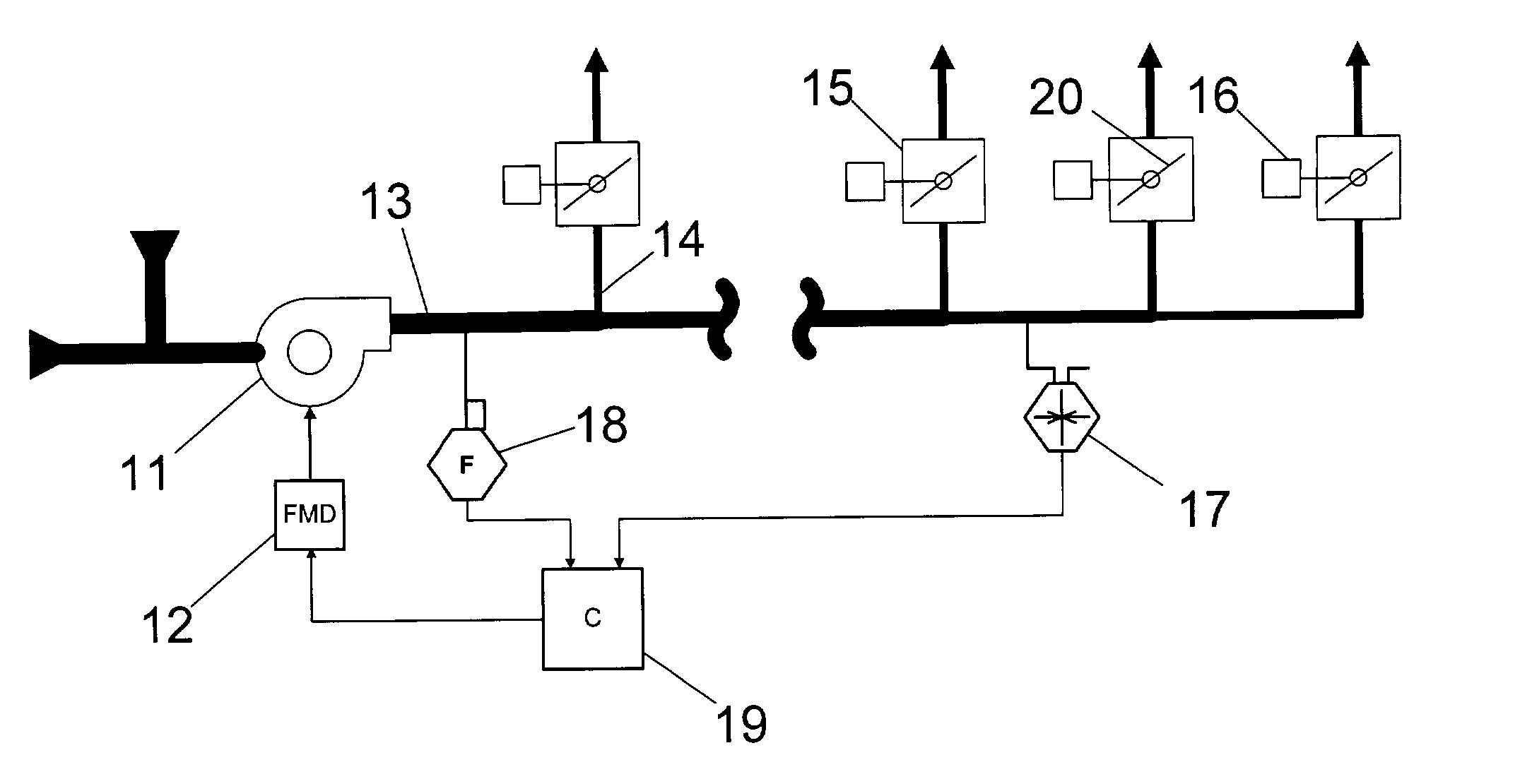
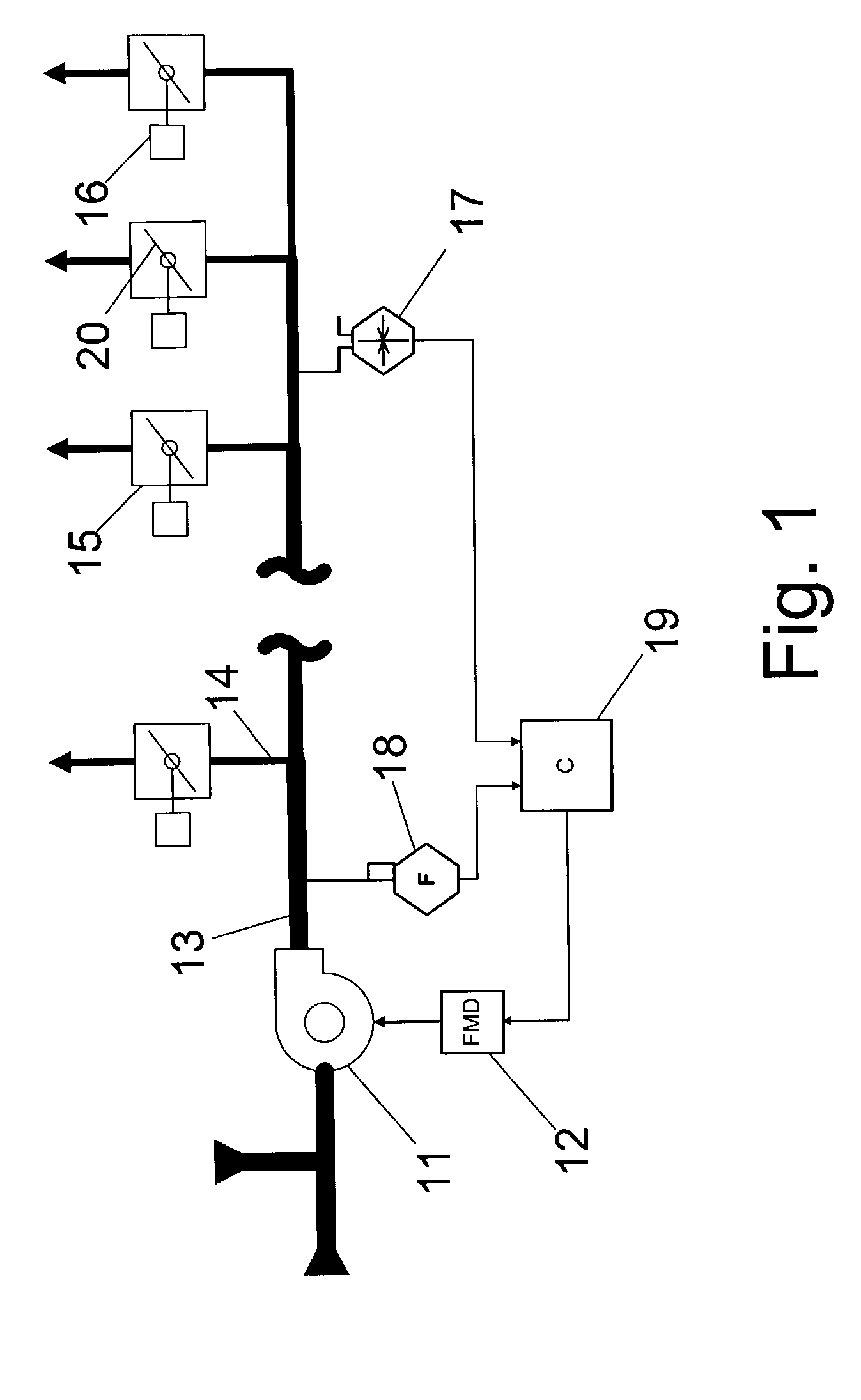
[0035] FIG. 4 shows a state transition diagram of an alternative embodiment for controlling the supply fan 11. In the alternative embodiment, the system has two modes: loss coefficient control mode 24 and constant pressure control mode 25. The loss coefficient control mode 24 has a loss coefficient calculator 26 which computes a loss coefficient, denoted as K, that is a function of the output of the static pressure sensor 17 and the output of the airflow sensor 18 as follows: 1 K = P Q n + C ( A )

[0036] where P denotes the output of the static pressure sensor 17, Q denotes the output of the airflow sensor 18, n is an exponent preferably between 1.0 and 2.0, and C is a constant used to ensure that the supply fan 11 will develop pressure and flow when the system is first turned on.

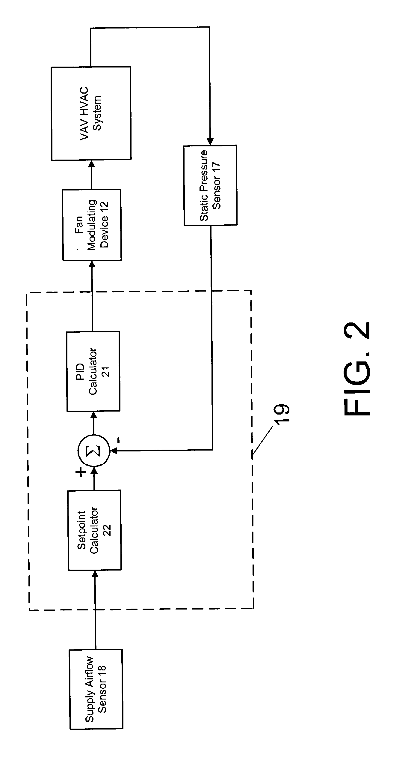
[0037] FIG. 5 shows a block diagram of the loss coefficient mode. The output of the static pressure sensor and the output of the airflow sensor ...


PUM


Abstract

A control strategy for supply fans in variable-air-volume heating, ventilating, and air-conditioning systems that reduces the static pressure at part-load conditions. The invention consists of a static pressure sensor, an airflow sensor, a supply fan, a fan modulating device, and a controller coupled to the static pressure sensor and the airflow sensor. The controller includes a calculator that calculates the static pressure setpoint as a function of the airflow rate. The static pressure setpoint is lower when the airflow rate is lower. The controller compares the static pressure setpoint with the static pressure, and it commands the fan modulating device so that the static pressure remains close to the static pressure setpoint. Alternatively, the controller includes a calculator that calculates a loss coefficient as a function of the static pressure and the supply rate. The controller compares the loss coefficient with a loss coefficient setpoint, and it commands the fan modulating device so that the loss coefficient remains close to the loss coefficient setpoint. When the airflow rate is sufficiently high, the alternative embodiment switches to a constant-pressure controller.

Description

[0001] This application claims benefit under Title 35, United States Code .sctn.1 19(e) of U.S. Provisional Application No. 60 / 325,070 filed on Sep. 26, 2001.[0002] 1. Field of the Invention[0003] The following invention relates to controls for variable-air-volume (VAV) heating, ventilating, and air-conditioning (HVAC) systems, specifically to control of a supply fan in VAV HVAC systems.[0004] 2. Description of the Prior Art[0005] Modern buildings typically have complex heating, ventilating, and air-conditioning systems to control indoor temperature, pressure, ventilation rate, and other variables in a way that makes efficient use of energy. One way to conserve energy in these systems is to use a so-called variable-air-volume design. Key components of a variable-air-volume system are a supply fan and terminal units. The supply fan is a prime mover that causes air to move. A terminal unit contains a throttling damper that regulates an amount of air supplied to a space in a building t...

Claims


Application Information

Patent Timeline
Patent Type & Authority Applications(United States)
IPC IPC(8): B61D27/00B64D13/00F04D27/02F24F3/044
CPCB61D27/00B64D13/00F04D27/004F24F3/0442Y02B30/767Y02B30/746Y02T30/42Y02T50/56F24F11/0079F24F11/77Y02B30/70Y02T30/00Y02T50/50
Inventor FEDERSPIEL, CLIFFORD CONRAD
Owner VIGILENT CORP
Why Eureka
Try Eureka