Reticle stage with reaction force cancellation

a technology of reaction force and stage, which is applied in the field of precision motion stages, can solve the problems of yaw, or rotation in the x-y plane, position degradation, and source of transmitted vibration through the reticle and stage to the underlying

Inactive Publication Date: 2003-04-10
NIKON CORP
View PDF0 Cites 15 Cited by
  • Summary
  • Abstract
  • Description
  • Claims
  • Application Information

AI Technical Summary

Problems solved by technology

"Yaw", or rotation in the X-Y plane, is another problem in conventional reticle stages.
Also, reticle stage technology has developed based on the recognition that the guide structure that was located in early reticle stage designs directly under the reticle stage interferes with directing light or an e-beam and may cause position degradation and a

Method used


Image

  • Reticle stage with reaction force cancellation
  • Reticle stage with reaction force cancellation
  • Reticle stage with reaction force cancellation

Examples


Embodiment Construction

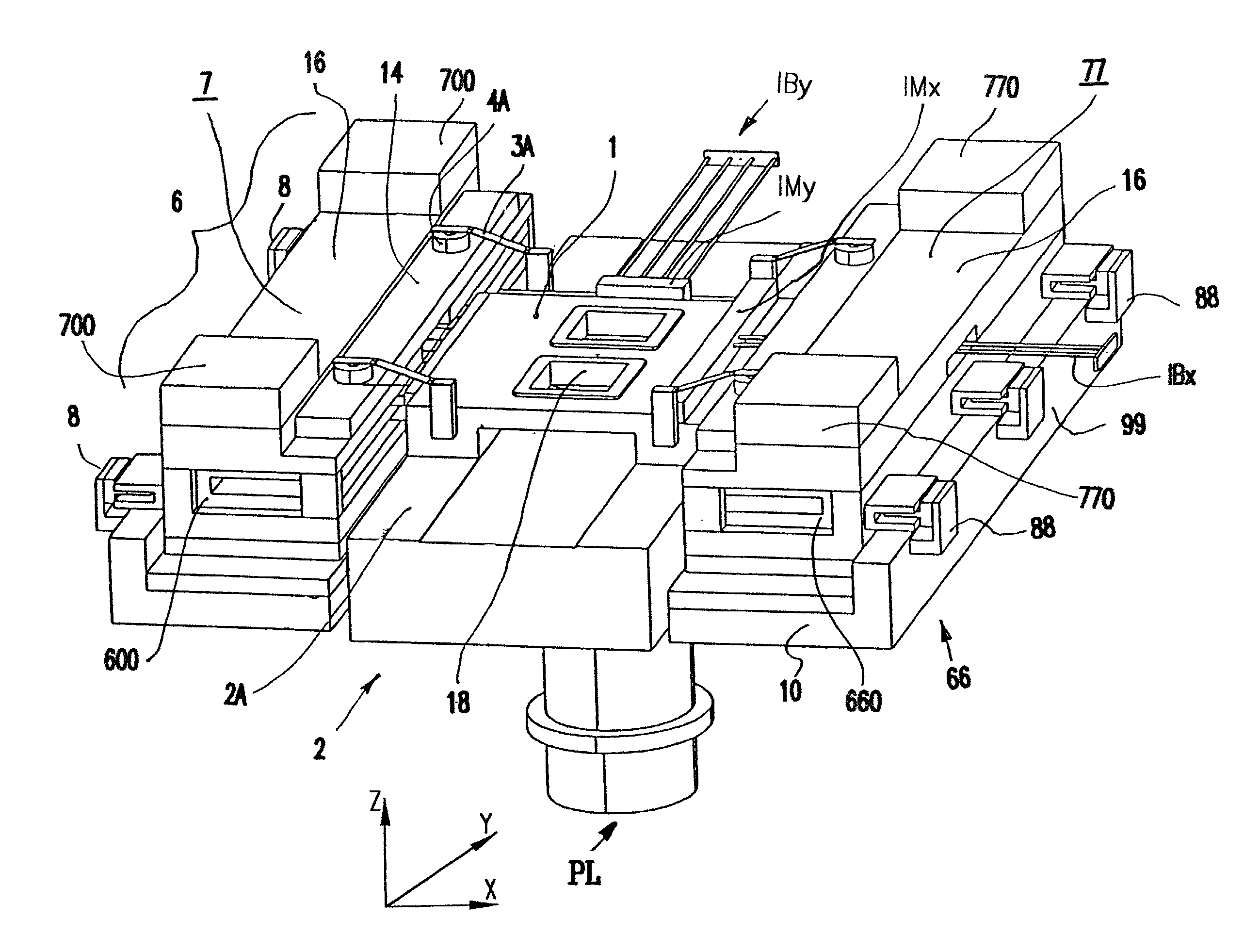
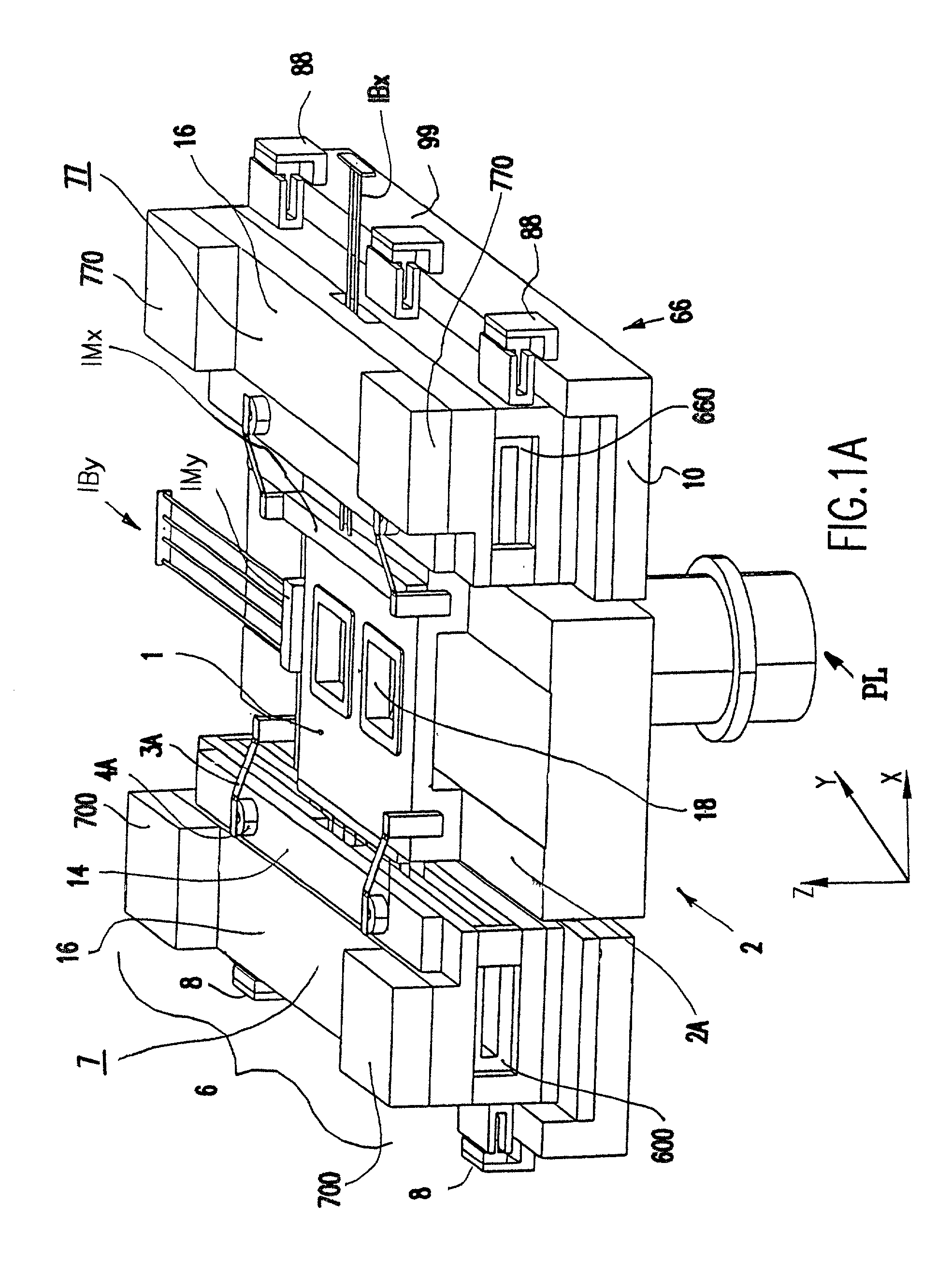
[0030] Referring now to the drawings, and more particularly to FIGS. 1A through 7E, there are shown photolithography apparatuses of exemplary form in accordance with preferred environments of the invention.

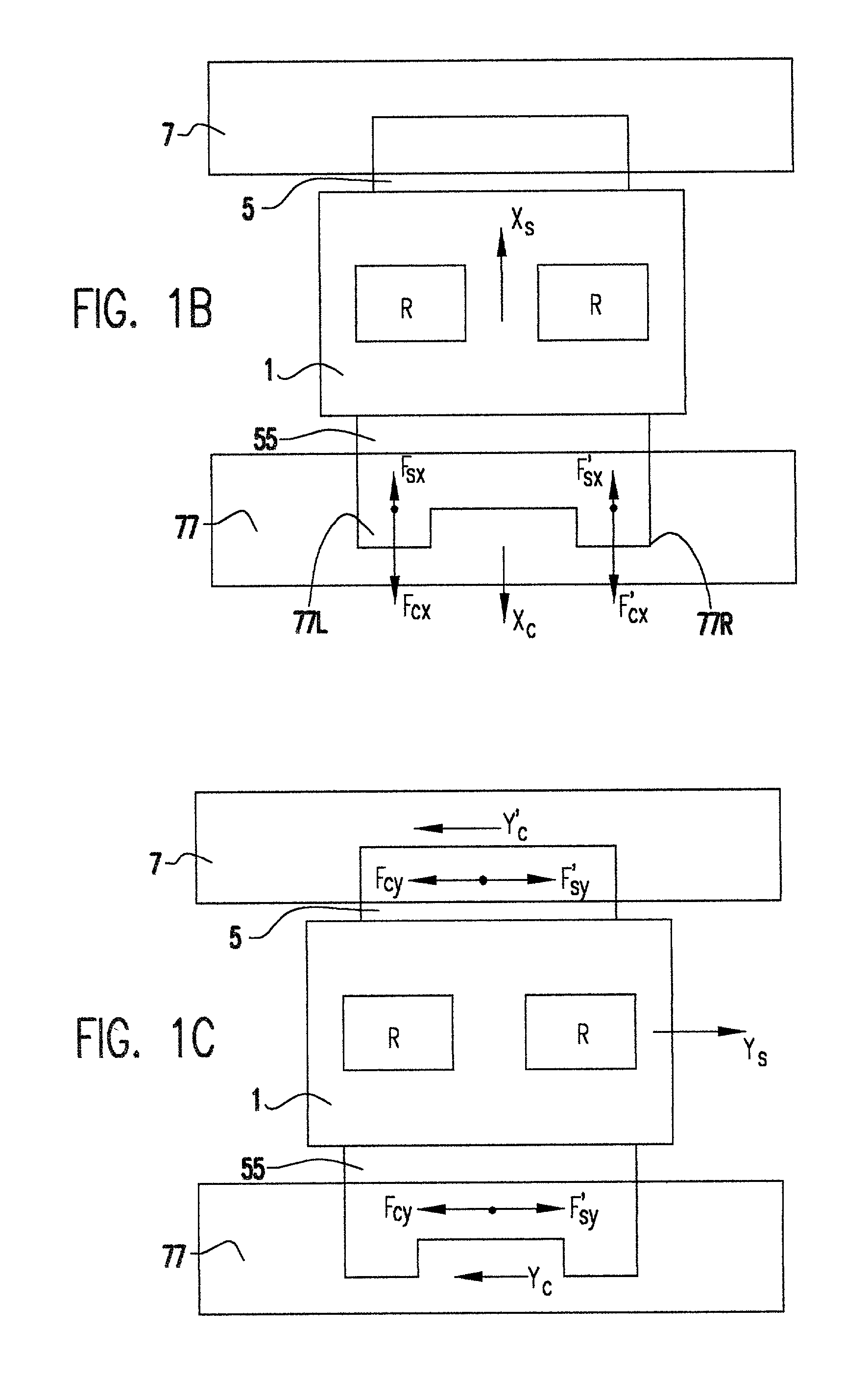
[0031] As shown in FIG. 1A, an exemplary apparatus according to the invention includes a reticle stage such as reticle stage 1 and a reaction force countermass assembly such as reaction force countermass assembly 6 or 66. The reticle stages 1 and reaction force-countermass assemblies 6, 66 shown in FIG. 1A may be modified and varied, such as variations shown in FIGS. 4 through 7E. The reticle stage 1 is coupled to a reaction force countermass assembly 6, 66 by air bearings 4A-4D of anti-gravity devices 3A-3D and magnetic fields generated by motors 5 and 55. Reticle stages 1, anti-gravity devices 3A-3D, and reaction force countermass assemblies 6, 66 are each discussed below, in turn.

[0032] The reticle stage 1 in FIG. 1A has a long Y, short X and small .theta..sub.z strokes. (In th...


PUM


Abstract

A three-degree-of-freedom guideless reticle stage is used with a reaction force-countermass assembly. An anti-gravity device such as a flexure is provided between the reticle stage and the reaction force-countermass assembly. The anti-gravity device offsets the weight of the stage to the reaction force-countermass assembly. Improved reticle-positioning is provided, with minimized distortion to the stage base, reduced forces on the frame, high servo bandwidth, three-degree-of-freedom positioning, high throughput, minimized geometry and low moving mass.

Description

[0001] 1. Field of the Invention[0002] This invention relates to precision motion stages and more specifically to a stage suitable for use in a lithography machine and especially adapted for supporting a reticle.[0003] 2. Description of the Prior Art[0004] In semiconductor manufacture, a medium such as light or non-visible radiation (e.g., DUV or a charged particle beam) is projected through a "reticle" (or mask) to pattern a resist on a wafer to allow selective processing. Positioning a reticle during these lithography processes has been accomplished by a stage that supports the reticle. An illumination system illuminates a reticle supported on a reticle stage and a lens system projects the reticle pattern on a target. The reticle has a specified pattern, such as a circuit, formed on the surface that is to be projected by a projection exposure system onto the surface of a wafer, while the wafer is positioned on a "wafer stage" separate from the reticle stage. Accurately positioning...

Claims


Application Information

Patent Timeline
IPC IPC(8): G03B27/62G03F7/20
CPCG03F7/70766G03B27/62
Inventor TIM POON, ALEX K.NOVAK, W. THOMAS
Owner NIKON CORP
Why Eureka
Try Eureka