However, some or all of the equipment, objects, and / or conditions are not intended to appear in the final product.
One of the difficulties of combining and integrating
computer graphics images into
live action scenes occurs during the second step of 3-D solving.
It is therefore very difficult to recreate and match the 3-D positioning and movement of the CGI to the recorded
live action scene.
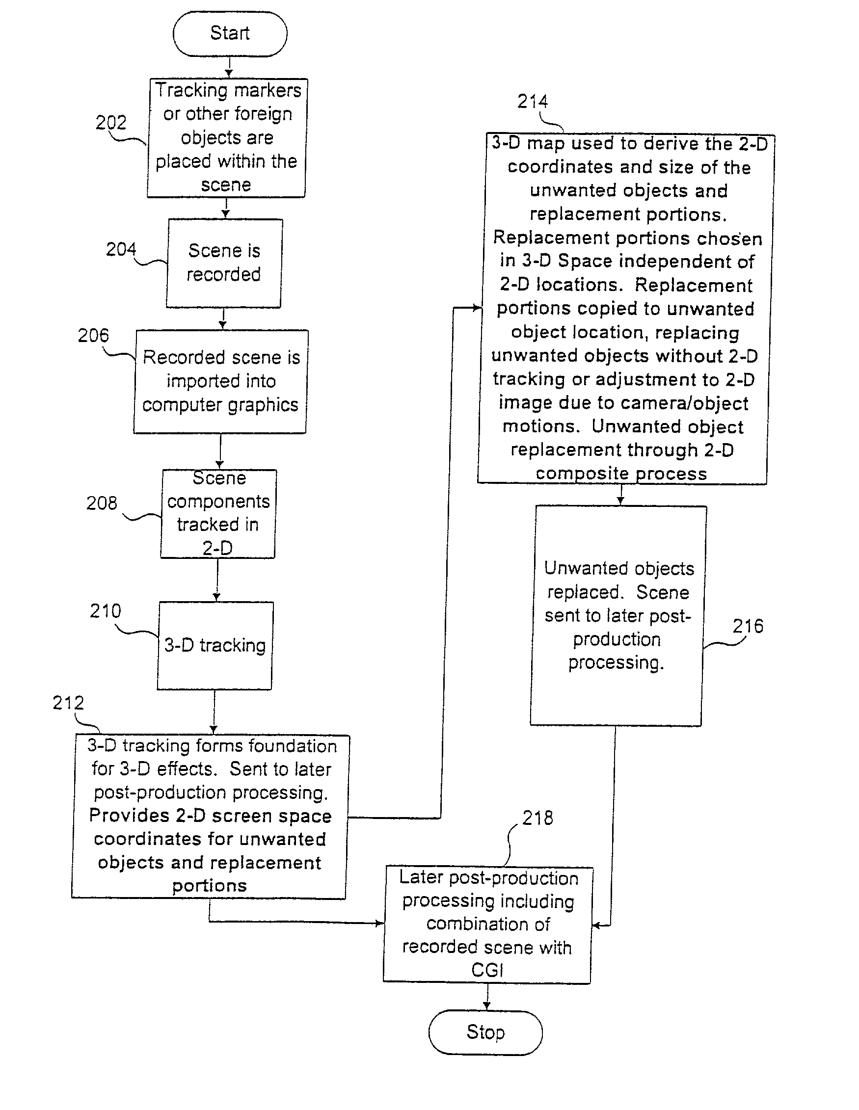
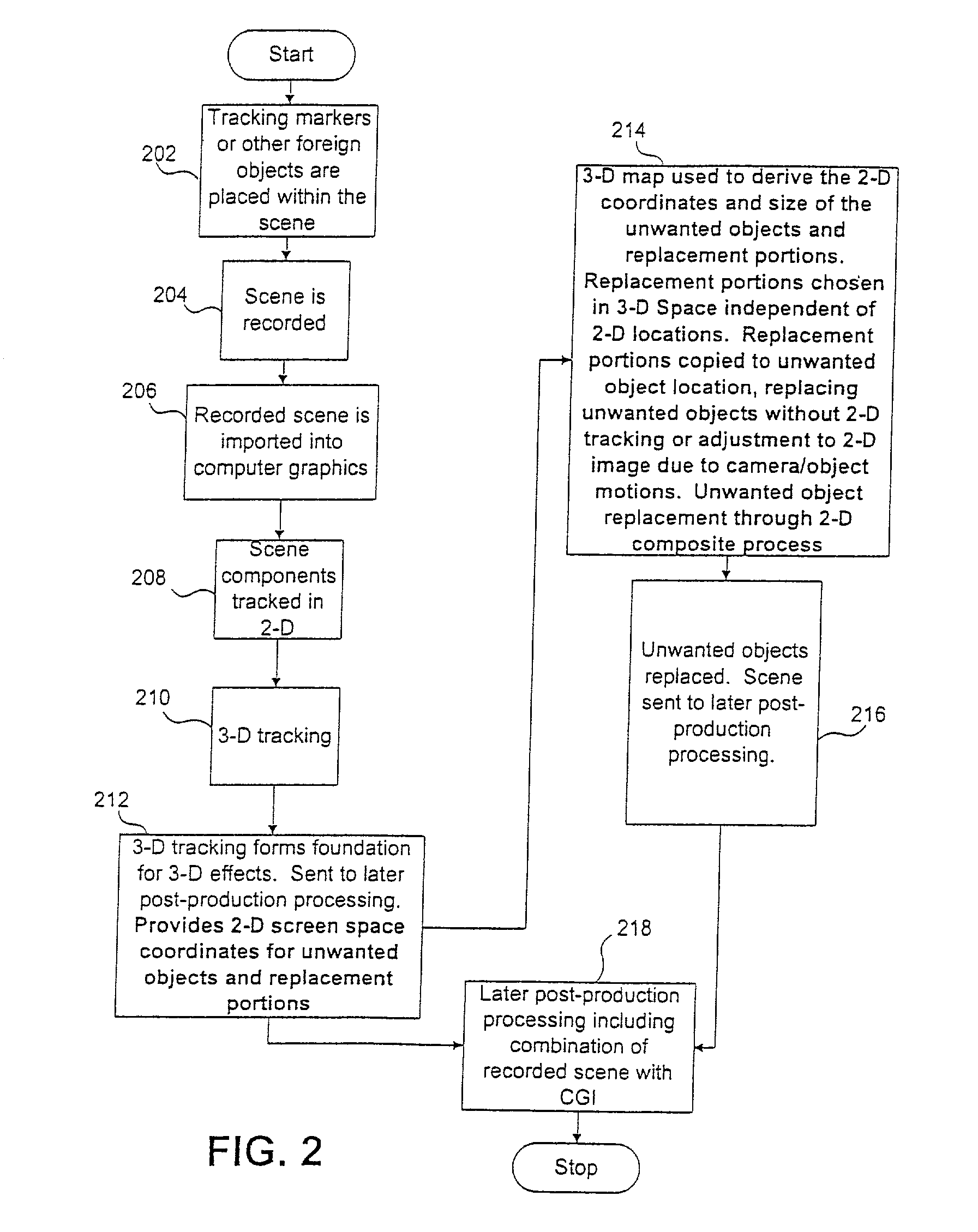
However, once the scene is recorded, the presence of the tracking markers in the scene becomes a problem along with any and all other foreign objects as described above.
Even if the scene is shot in a normal environment such as a room or outdoor location and there are no other objectionable objects such as lighting equipment, the tracking markers are a problem which must be corrected by removing them from the original image.
Unfortunately, there are a number of problems and practical considerations which make the
motion control solution undesirable, impractical, too expensive, or even impossible.
Some of the factors which make the
motion control pass solution unacceptable include:
noise from the motors which can cause problems for sound recording; the need for much more expensive and complicated camera equipment and a specialized
crew to run the equipment; the motors moving the camera have speed limits which can present problems compared to normally operated camera motions; the setup time and time to
shoot the extra passes greatly
impact the
production schedule and further raises costs and concerns; and the equipment itself is not foolproof.
Furthermore, if the passes are not absolutely identical, the second reference pass with the markers is useless and the
special effects may therefore become enormously more complex without their presence to assist in the 3-D solve, thereby defeating any potential saving or other consideration gained through the use of
motion control.
Because of these problems and the additional expense and complexity of motion control, the solution is considered too expensive and potentially faulty compared to the use of markers and other equipment which can be replaced through standard post-production
special effects methods.
Moreover, it is sometimes advantageous to determine more than one replacement portion to be associated with a particular tracking marker dot.
However, even when using a 2-D tracking program there may still be a considerable number of manual steps involved in order to
overlay (i.e.,replace) the original tracking marker dots in a satisfactory manner.
These variations may result in portions of the tracking markers not being fully overlaid by the replacement portions.
If they are not consistent, negative effects such as
flicker, inconsistent color change, or wobble may occur in that portion of the scene where the tracking marker was overlaid.
Such effects may be discernible by a viewer and are usually unacceptable.
Commonly, it is difficult to perform 2-D tracking on the source because the source may not stand out in the scene in the same manner as the tracking marker dot or marker whose characteristics are specially designed to make tracking easy and accurate.
However trying to track any specific patch of grass alone is extremely difficult since one area will look virtually the same as another as a scene progresses.
The high precision tracking necessary for realistic
computer graphics effects may become extraordinarily difficult or nearly impossible in this or similar types of situations.
This is because accurate tracking requires discernible differences to distinguish one area from another, and either human or computer-assisted tracking will have great difficulty in tracking one specific grassy area because of the lack of trackable differences in the grassy field."
Thus, it is often difficult to accurately and efficiently track the source and maintain this consistency when employing a 2-D tracking program because unlike in the case of the tracking marker there is usually no consistent frame-to-frame tracking point which the 2-D tracking program can utilize to track the replacement portions.
The replacement process may be further complicated in several ways.
For example, if the tracking markers are placed on a moving object within the scene, for example a tumbling automobile, the replacement process becomes much more complex.
Furthermore, the process is more complicated when the camera move is not a simple one.
More complex camera moves in relation to the recorded object may result in changes in the 2-D
spatial relationship of the sources to the targets from frame-to-frame, as well as possibly changing the size of the sources and targets.
Also, additional complexity may be introduced if the object is moving at the same time that the camera is moving.
This makes consistent
copying of the source pixels over the target pixels very difficult in a automated 2-D tracking process.
As a result, the CGI artist must work with a less accurate 3-D model.
Although the previous example focused on tracking markers, as mentioned earlier, special effects scenes oftentimes contain many foreign objects, such as stage rigging,
safety equipment, incomplete buildings, and other portions of the scene which are undesirable, and which must be replaced through some technique.

