
Work fixing clamp system

a technology of clamp system and clamping plate, which is applied in the direction of positioning apparatus, metal-working machine components, manufacturing tools, etc., can solve the problems increasing the difficulty of increasing the work area ratio, and complex structure of the clamp system, so as to simplify the structure simplify the design and processing, and simplify the effect of the first oil path

Inactive Publication Date: 2003-05-22
PASCAL ENG
View PDF7 Cites 16 Cited by
  • Summary
  • Abstract
  • Description
  • Claims
  • Application Information

AI Technical Summary

Benefits of technology

[0022] The guide member, which covers the majority of the portion of the piston rod projecting out from the base plate surface while not obstructing the clamping action of the output member, guides the piston rod so that it can move back and forth and allows the output member to reliably press and clamp the workpiece against the base plate. Since the guide member covers the majority of the projected portion of the piston rod, elastic deformation of the piston rod during the clamped state is prevented and deformation of the workpiece is prevented. Furthermore, the piston rod is protected from external dust such as debris from machining.
[0036] The first oil path includes: a clamping oil path for clamping the plurality of clamp devices; and an unclamping oil path for releasing the clamped state of the plurality of clamp devices. These clamping oil paths and unclamping oil paths can be arranged separated from each other along the axis perpendicular to the surface of the base plate. The space along the axis parallel to the surface of the base plate used to form the first oil path can be made compact.

Problems solved by technology

Thus making the base plate more compact and increase the work area ratio is difficult.
Furthermore, since hydraulic pipes must be connected to the main cylinder units of the plurality of clamp devices in order to supply hydraulic pressure, the structure of the clamp system is made more complex, and production costs are increased.
Also, the system may go down if the hydraulic pipes extending from the clamp devices are damages.
If a double-action hydraulic clamp device is used, a large number of hydraulic pipes will be used, further increasing the problems.
This makes the structure of the oil paths more complex and involve complicated design and processing operations.
When these spacers are used, there may be oil leakage from the connection points of the oil paths of the spacers.
Referring to FIG. 14, in this clamp system, hydraulic pipes must be provided to supply hydraulic pressure to the clamp devices, thus leading to problems similar to those of the clamp system from FIG. 12.
As a result, the structure of the oil paths becomes very complex.
Furthermore, the design and processing operations must take into account interference between the clamping oil paths and the unclamping oil paths, making the operations very complex.
Also, if the clamp devices are disposed around the edges of the base plate, a relatively large space is required to form the oil paths at the edges for the clamp devices.
Thus, the base plate cannot be made compact and the work area ratio cannot be increased.
Thus, when the piston rod is to be extended, the provided guiding ability is not adequate, which can tend to produce elastic deformation in the piston rod.
Also, the piston rod cannot be adequately protected from debris from machining and other external dust.

Method used


Image

  • Work fixing clamp system
  • Work fixing clamp system
  • Work fixing clamp system

Examples


Embodiment Construction

[0054] Referring to the figures, the following is a description of the embodiments of the present invention.

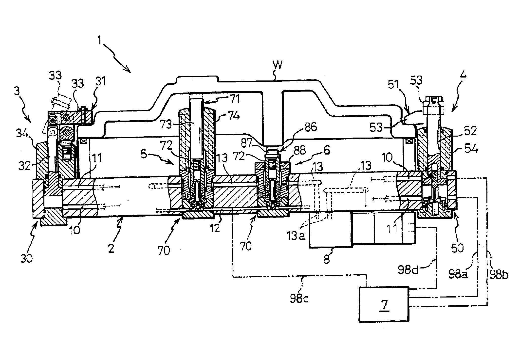
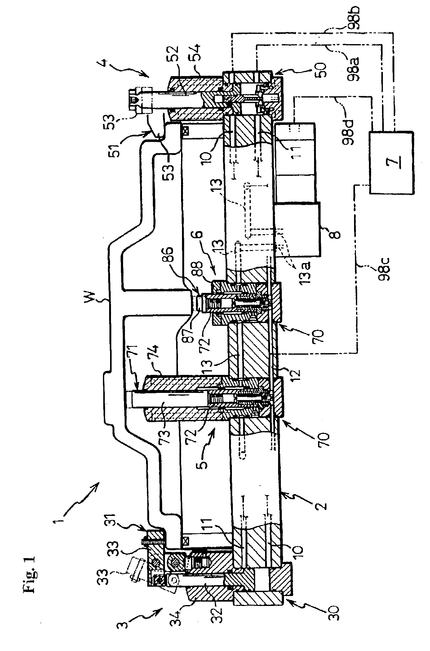
[0055] This embodiment is an example wherein the present invention is implemented in a clamp system for securing a workpiece that removably secures a workpiece on a base plate using a plurality of hydraulic clamp devices. In this clamp system, the base plate is oriented horizontally. In the following description, references to up / down / left / right will be based on the directions relative to FIG. 1.

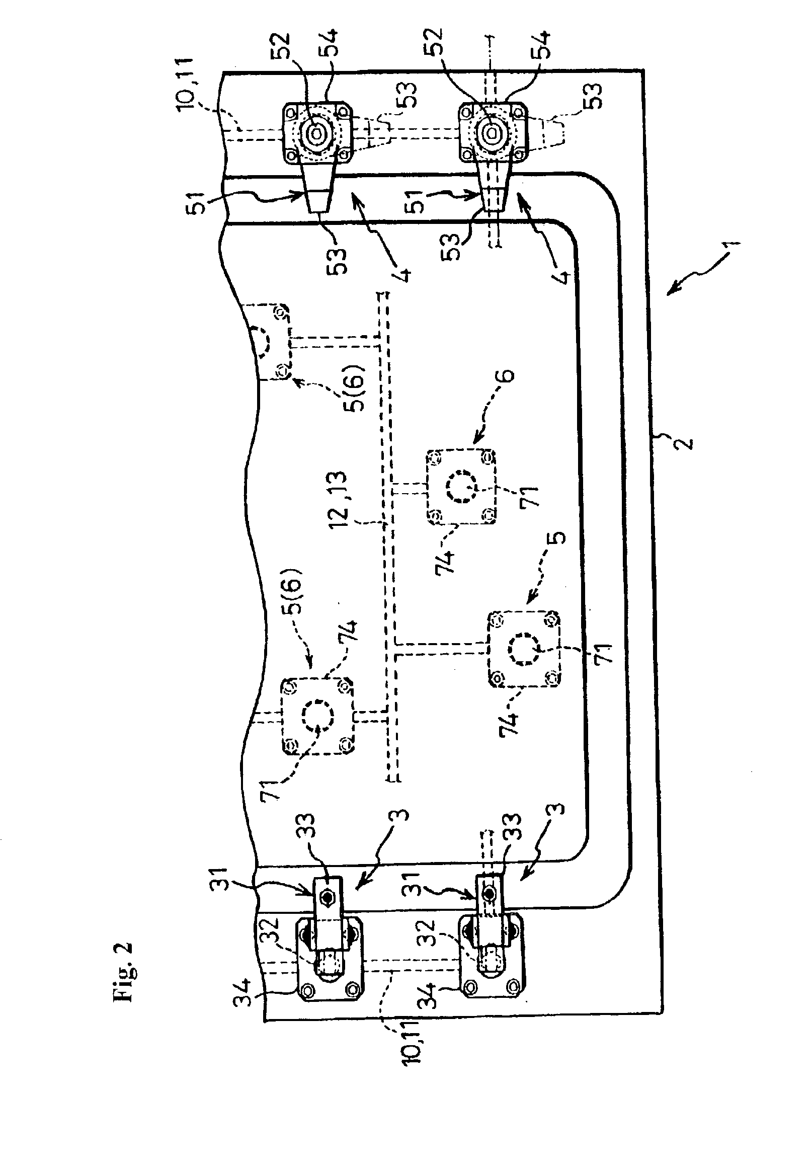
[0056] Referring to FIG. 1 and FIG. 2, a workpiece-securing clamp system 1 (hereinafter referred to as the clamp system 1) includes: a thick base plate 2 (e.g., a base plate 2 having a predetermined thickness of approximately 4 to 8 cm) equipped with a plurality of hydraulic clamp devices 3, 4 for securing a workpiece W; a plurality of vertically pivoting hydraulic clamp device 3 and a plurality of horizontally pivoting hydraulic clamp devices 4 mounted on the base plate 2; a plurality...


PUM


Abstract

The present invention provides a clamp system for securing a workpiece. The structure of oil paths formed in a base plate is simplified while maintaining good guiding ability of a piston rod of a hydraulic cylinder. Also, the ratio of the work area relative to the surface of the base plate is increased. Hydraulic clamp devices (3, 4) include: main cylinder units (30, 50) mounted vertically in a base plate (2); output members (31, 51) including piston rods (32, 52) extending from the main cylinder units (30, 50) toward the surface of the base plate (2); guide members (34, 54) disengageably secured to the surface of the base plate (2) and guiding the piston rods (32, 52) so that they can be moved back and forth; and rod-side cylinder end walls (41, 61) of the main cylinder units (30, 50) disengageably secured to the base plate (2). First oil paths (10, 11) formed in the wall of the base plate (2) supply hydraulic pressure from the hydraulic pressure supply device (7) to the main cylinder units (30, 50) of the plurality of clamp devices (3, 4).

Description

[0001] The present invention relates to a clamp system for securing a work piece that removably secures a workpiece on a base plate using a plurality of hydraulic clamp devices. More specifically, the present invention relates to a device wherein main cylinder units of a plurality of clamp devices are built into a base plate, with hydraulic pressure being provided to these main cylinder units via hydraulic paths formed in the walls of the base plate.BACKGROUND TECHNOLOGY[0002] Referring to FIG. 12, standard clamp systems for securing workpieces conventionally include a base plate 200 and a plurality of hydraulic clamp devices 210 attached to the base plate 200. These clamp devices 210 disengageably secure a workpiece Wa mounted on the base plate 200. Various machining operations and the like can then be performed on the workpiece Wa.[0003] The clamp device 210 includes: a main cylinder unit 211; an output member 212 including a piston rod 213 extending upward from the main cylinder ...

Claims


Application Information

Patent Timeline
IPC IPC(8): B25B5/00B25B5/06B23Q3/06B25B5/12
CPCB25B5/003B25B5/122B25B5/064B25B5/061
Inventor KITAURA, ICHIRO
Owner PASCAL ENG
Learn More