
Method and device for reducing influence of early effect

a technology of early effect and reducing influence, which is applied in the direction of electronic switching, amplifiers with impedence circuits, pulse techniques, etc., can solve the problems of reducing the settling time, and reducing the settling speed, so as to reduce the influence

Inactive Publication Date: 2003-05-22
TEXAS INSTR INC
View PDF38 Cites 4 Cited by
  • Summary
  • Abstract
  • Description
  • Claims
  • Application Information

AI Technical Summary

Benefits of technology

[0013] In order to realize the aforementioned objectives, the method using a three-terminal device of this invention is characterized by the fact that it can reduce the influence of the Early effect pertaining to said three-terminal device in the operation of a circuit containing the three-terminal device.
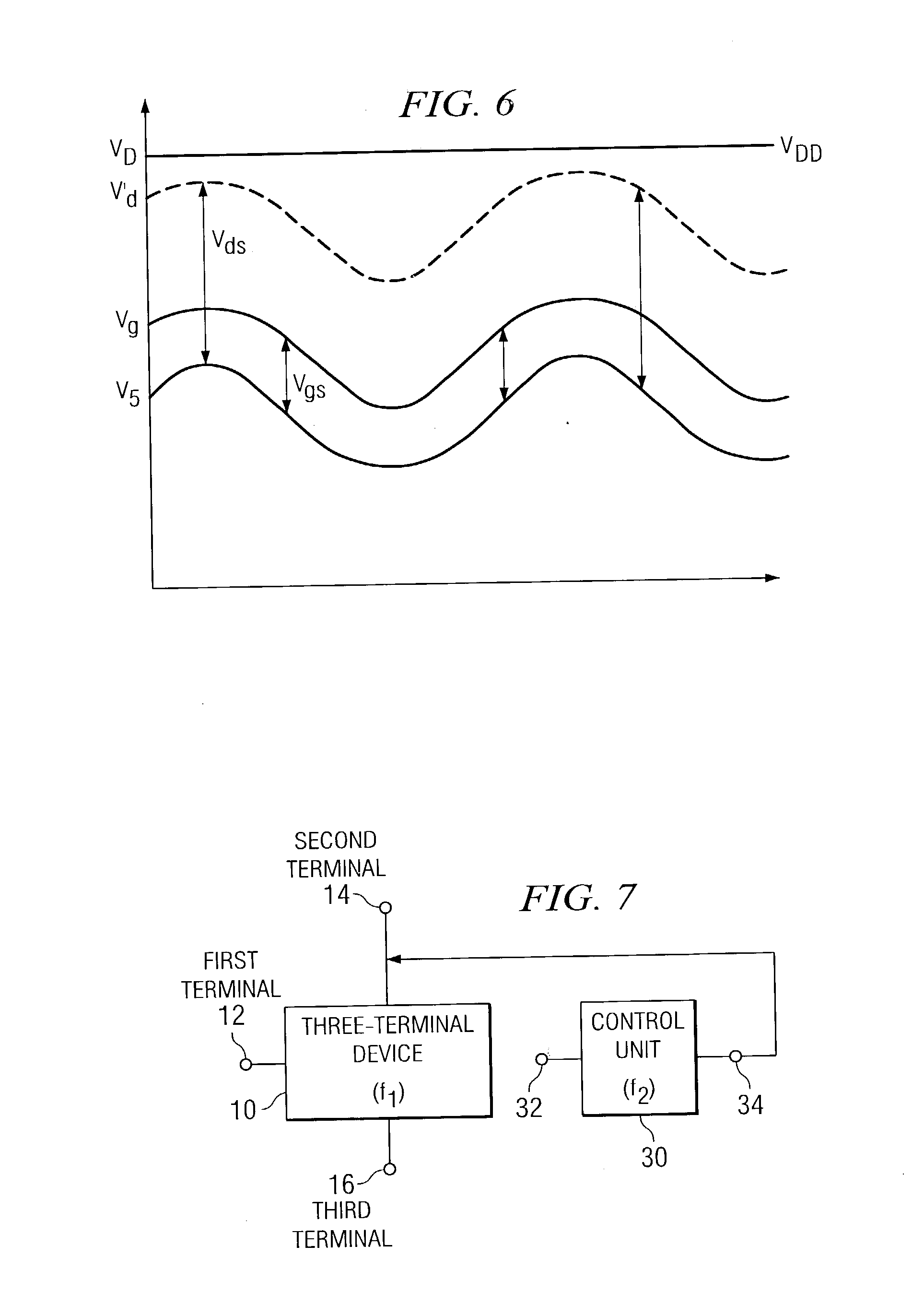
[0016] Also, the Early effect component reducing method of this invention is characterized by the following facts: the method is for reducing the Early effect component in the output signal of a three-terminal device, which has a first terminal and second terminal acting as input terminals and a third terminal acting as output terminal, and which generates an output signal to the third terminal as a response to the input signal input to the first terminal; by controlling the potential of the second terminal of the device as a response to the first terminal pertaining to the input signal received in the first terminal, the first potential difference (Vds) between the second terminal and the third terminal of the device is essentially kept constant.
[0019] Also, the signal buffer method, in which the signal is buffered using a buffer circuit containing a three-terminal device is characterized by the fact that the Early effect component pertaining to the three-terminal device is reduced in the operation of the buffer circuit.
[0021] Also, the Early effect component reducing circuit of this invention is characterized by the following facts: the Early effect component reducing circuit is for reducing the component due to the Early effect in the output signal of a three-terminal device, which has a first terminal and second terminal acting as input terminals and a third terminal acting as output terminal and which generates an output signal on the third terminal as a response to the input signal input to the first terminal; it has a control means that receives the first signal pertaining to the input signal and controls the potential of the second terminal of the device as a response to the first signal; in this way, the first potential difference (Vds) between the second terminal and the third terminal of the device is kept essentially constant so that the Early effect component is reduced.

Problems solved by technology

However, for a closed loop buffer using an operational amplifier, because it has a feedback loop, it is hard to realize high speed of operation.
Also, for such closed loop buffer, even when a bipolar processor is used, a commercially available general-purpose IC can only realize a settling time of about tens of ns, and it is hard to realize a settling time one order of magnitude shorter, that is, several ns.
Also, in a closed loop buffer using a CMOS process, there is no way to realize a settling time of several ns.
Also, since it is used with feedback applied on it, if no particularly special process is used, there is no way to expect a high speed of operation.
In addition, if the DC gain of the amplifier is raised or the magnitude of the input differential transistor is increased to reduce the offset, the operation speed further falls.
Even when an up-to-date CMOS process is used, it is still extremely hard to realize a settling time of a few ns for 12-bit operation.
On the other hand, for an emitter follower as an open loop buffer, although the speed is high, gain error and harmonic distortion are significant, so that the precision is poor.
However, if variation in the input signal is high, the influence of variation in Vds cannot be ignored.
Consequently, gain error takes place.
Also, because the signal dependence of Vgs is not completely linear, harmonic distortion takes place in the output.
However, as aforementioned, there is a problem with respect to precision.

Method used


Image

  • Method and device for reducing influence of early effect
  • Method and device for reducing influence of early effect
  • Method and device for reducing influence of early effect

Examples


Embodiment Construction

[0039] In the following, this invention will be explained in detail with reference to figures.

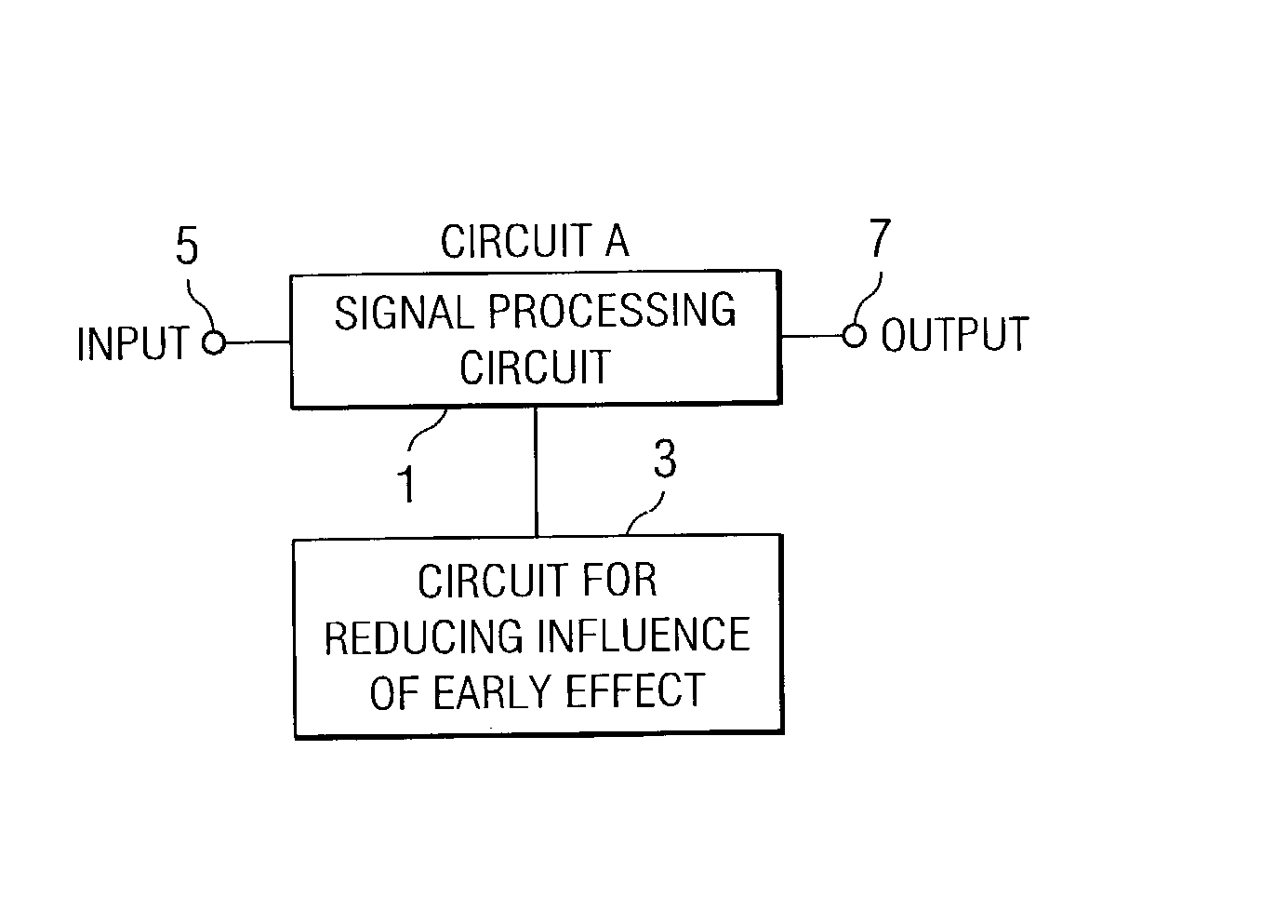
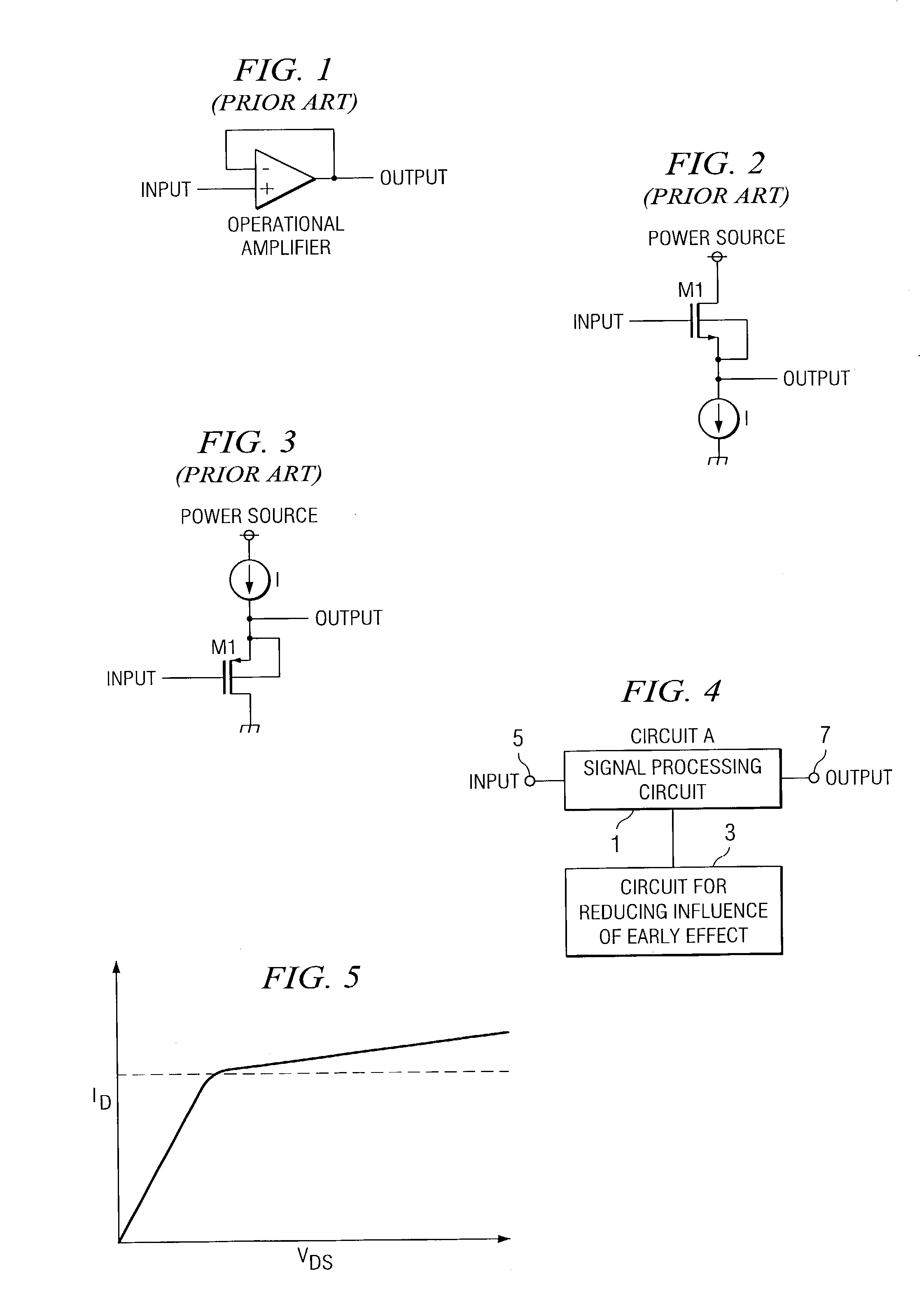
[0040] First of all, the basic concept of use of a three-terminal device in this invention will be considered with reference to FIG. 4. As shown in FIG. 4, circuit A includes any signal processing circuit 1 containing a three-terminal device (not shown in the figure), and Early effect component reducing circuit 3 for improving performance of said signal processing circuit. This signal processing circuit includes a buffer circuit, analog circuit or mixed signal circuit containing said buffer circuit, other processing circuits, etc. This signal processing circuit 1 has an input signal received with its input terminal 5 and generates an output signal at its output terminal 7 after processing of the input signal. According to this invention, in order to increase the signal processing speed, precision, and other properties in signal processing circuit 1, Early effect component integral reducing ...


PUM


Abstract

A method is provided for improving the performance of a circuit containing a three-terminal device. In the operation of a circuit containing three-terminal device 10, the influence of the Early effect pertaining to the three-terminal device of a FET is reduced. In order to reduce the influence, control unit 30 is set for reducing the Early effect component caused by a three-terminal device. As a result, by controlling the potential of the second terminal (such as drain) of the device as a response to a first signal pertaining to the input signal received by the first terminal (such as gate) of the device, it is possible for the potential difference between the second terminal (drain) and the third terminal (such as source) of the device to be essentially constant.

Description

[0001] This invention pertains to a method for using a three-terminal device, and a circuit for applying said method. Also, this invention pertains to a method and circuit for reducing the influence of the Early effect of a three-terminal device, and a buffer or another circuit that uses said method or circuit.[0002] In the prior art, closed loop buffers using operational amplifiers have been used for high-precision buffering. Also, open loop buffers represented by an emitter follower are also in use.[0003] However, for a closed loop buffer using an operational amplifier, because it has a feedback loop, it is hard to realize high speed of operation. Also, for such closed loop buffer, even when a bipolar processor is used, a commercially available general-purpose IC can only realize a settling time of about tens of ns, and it is hard to realize a settling time one order of magnitude shorter, that is, several ns. Also, in a closed loop buffer using a CMOS process, there is no way to r...

Claims


Application Information

Patent Timeline
Patent Type & Authority Applications(United States)
IPC IPC(8): H03F1/14H03F3/50H03F1/30
CPCH03F1/301H03F1/14
Inventor NITTA, SHOZO
Owner TEXAS INSTR INC
Learn More