Matrix type piezoelectric/electrostrictive device and manufacturing method thereof

a piezoelectric/electrostrictive element, matrix-type technology, applied in the direction of piezoelectric/electrostrictive device details, device material selection, instruments, etc., can solve the problem of difficult to increase displacement and force generation at the same time, and the stress which causes the strain of the piezoelectric/electrostrictive element cannot be directly utilized,

Inactive Publication Date: 2003-05-29
NGK INSULATORS LTD
View PDF2 Cites 48 Cited by
  • Summary
  • Abstract
  • Description
  • Claims
  • Application Information

AI Technical Summary

Problems solved by technology

However, since the bending displacement element converts strain, stress which causes the strain of the piezoelectric/electrostrictive element cannot be directly utilized.
Therefore, it is very difficult to increase displacement and force generation at the same time.
Moreover, since the resonance frequency is inevitably decreased as the length of the element is increased, it is also difficult to satisfy a desired response speed.
However, since an increase in the contact area causes reliability relating to separation to be decreased, a piezoelectric/electrostrictive device capable of generating a large force is necessary as the actuator section.
Since this piezoelectric actuator has a structure in which driver electrodes are stored in the piezoelectric element in advance, an electrode-piezoelectric material stacked structure of each of the piezoelectric elements becomes non-uniform due to the influence of strain during sintering.
This causes characteristics of the elements to become uneven.
Since t

Method used


Image

  • Matrix type piezoelectric/electrostrictive device and manufacturing method thereof
  • Matrix type piezoelectric/electrostrictive device and manufacturing method thereof
  • Matrix type piezoelectric/electrostrictive device and manufacturing method thereof

Examples


Embodiment Construction

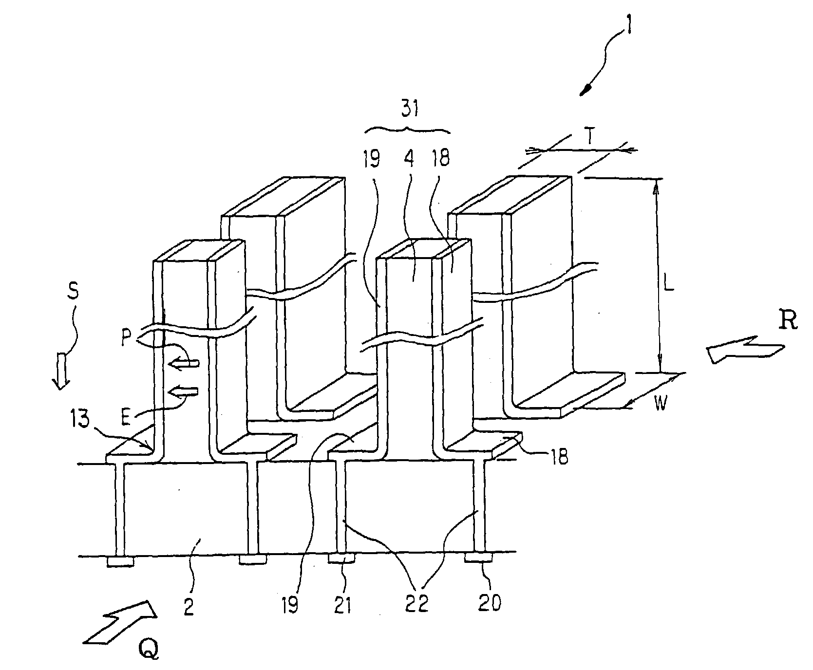
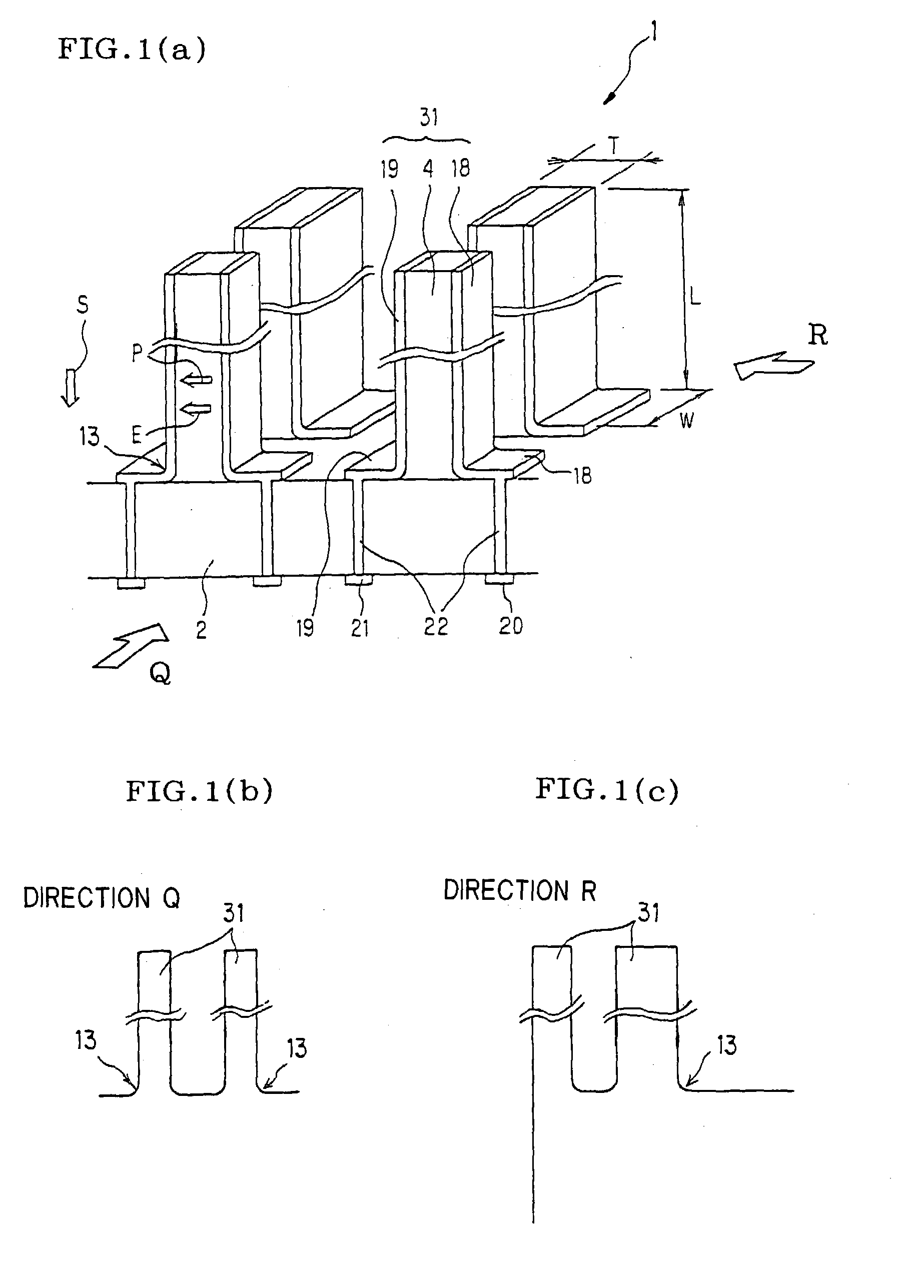
[0072] Embodiments of a matrix type piezoelectric / electrostrictive device of the present invention and a method of manufacturing the same are described below in detail. However, these embodiments should not be construed as limiting the scope of the present invention. Various modifications, revisions, and improvements are possible within the scope of the present invention based on the knowledge of a person skilled in the art.

[0073] The matrix type piezoelectric / electrostrictive device according to the present invention is a unit which attains collective functions by utilizing strain induced by an electric field. The matrix type piezoelectric / electro-strictive device includes an actuator, a sensor, and the like having a piezoelectric / electrostrictive element as a constituent element. The matrix type piezoelectric / electrostrictive device according to the present invention is not limited to piezoelectric / electrostrictive devices which utilize a piezoelectric effect which produces strain...


PUM

PropertyMeasurementUnit
Fractionaaaaaaaaaa
Fractionaaaaaaaaaa
Thicknessaaaaaaaaaa

Abstract

A matrix type piezoelectric/electrostrictive device in which a plurality of piezoelectric/electrostrictive elements almost in a pillar shape, each having a piezoelectric/electrostrictive substance and at least a pair of electrodes, are vertically provided on a thick ceramic substrate, and which is driven by displacement of the piezoelectric/electrostrictive substance. In this matrix type piezoelectric/electrostrictive device, a plurality of piezoelectric/electrostrictive elements are integrally bonded to the ceramic substrate and independently arranged in two dimensions. The pair of electrodes is formed on the sides of the piezoelectric/electrostrictive substance. The percentage of transgranularly fractured crystal grains on at least the sides of the piezoelectric/electrostrictive substance on which the electrodes are formed is 10% or less. The piezoelectric/electrostrictive substance forms a curved surface near a joined section between the piezoelectric/electrostrictive substance and the ceramic substrate. According to this piezoelectric/electrostrictive device, large displacement is obtained at a low voltage, with achievement of a high speed response, a large force generation, excellent mounting capability, a higher degree of integration. The action such as pushing, distorting, moving, striking (impacting), or mixing can be applied to an object of action, or the device operates when such action is applied.

Description

BACKGROUND OF THE INVENTION AND RELATED ART[0001] The present invention relates to a matrix type piezoelectric / electrostrictive device. More particularly, the present invention relates to a matrix type piezoelectric / electrostrictive device which is used for an optical modulator, optical switch, electrical switch, microrelay, microvalve, transportation device, image display device such as a display and a projector, image drawing device, micropump, droplet discharge device, micromixer, microstirrer, microreactor, various types of sensors, and the like, generates large force and large displacement, allows a piezoelectric / electro-strictive substance to generate expansion / contraction displacement or expansion / contraction vibration in a direction perpendicular to a main surface of a ceramic substrate by a transverse effect of an electric field induced strain of the piezoelectric / electrostrictive substance, and applies action such as pushing, distorting, moving, striking (impacting), or mi...

Claims


Application Information

Patent Timeline
IPC IPC(8): G02B6/12G02B6/35G02B26/00G02B26/02H05B3/44G02B26/08H01J5/48H01J5/50H01J5/54H01L27/20H01L29/82H01L41/04H01L41/08H01L41/09H01L41/18H01L41/187H01L41/193H02N2/00H04R17/00H05B3/02H05B3/06
CPCG02B6/12004G02B26/0858H01J5/54Y10T29/42H01L41/43H01L41/0986H01L41/338H01L27/20H10N39/00H10N30/206H10N30/088H10N30/097
Inventor TAKEUCHI, YUKIHISAWATANABE, MASASHIKIMURA, KOJIKAWAGUCHI, TATSUO
Owner NGK INSULATORS LTD
Why Eureka
Try Eureka