Imaging system using color sensors and tunable filters

a color sensor and color filter technology, applied in the field of color imaging systems, can solve the problems of insufficient information, inability to accurately match the image produced by the detector to the human eye's perception, and inability to accurately reproduce color for real-world samples

Inactive Publication Date: 2003-05-29
CAMBRIDGE RES & INSTR
View PDF11 Cites 39 Cited by
  • Summary
  • Abstract
  • Description
  • Claims
  • Application Information

AI Technical Summary

Problems solved by technology

These sensors acquire color images, but the color rendition is not always accurate for real-world samples.
Since the detector has color weightings that are not equal to those of the standard observer, nor to a linear combination of the standard observer functions, the image produced by the detector cannot be well-matched to the human eye's perception, no matter what linear algebraic steps are applied to the images.
There simply is not enough information to do so, since the detector samples the colors with the wrong weighting of wavelengths, and one cannot determine what the colors actually were, after the fact.
Current technology does not provide means for matching the RGB spectral response to the tristimulus curves, or to a linear combination thereof.
Because the spectral response of the detector is mismatched to how the human eye perceives the scene, the color fidelity is degraded by the acquisition process.
This achieves a high degree of color fidelity, but it is only suitable for use with scanners or inert objects that can be kept fixed for the time required to complete two or more scans, along with the intervening analysis to determine what filter is optimum.
This approach has several problems.
The filter has significant cost, complexity, and thickness.
In addition, light loss in the filter is considerable.
The result is lower transmission, which means the system is less sensitive and does not work as well in dim scenes.
Color blur is objectionable because it tends to produce brightly-hued edges on moving objects, an effect which is quite unparalleled in ordinary life.
Except for a few specialized (and expensive) high-speed models, common imaging detectors such as CMOS, CCD, and CID detectors take several milliseconds to read out.
Since the detector must be read-out and the filter must be tuned between each successive exposure, the overall acquisition of a color image takes well in excess of 1 ms, making it impractical to use conventional flash lighting.
Thus, presently all systems that provide for color image capture suffer from a significant loss in color fidelity, or are incompatible with flash lighting, or suffer from at least one of the following limitations: excessive cost, thickness, and light loss in the optics.

Method used


Image

  • Imaging system using color sensors and tunable filters
  • Imaging system using color sensors and tunable filters
  • Imaging system using color sensors and tunable filters

Examples


Embodiment Construction

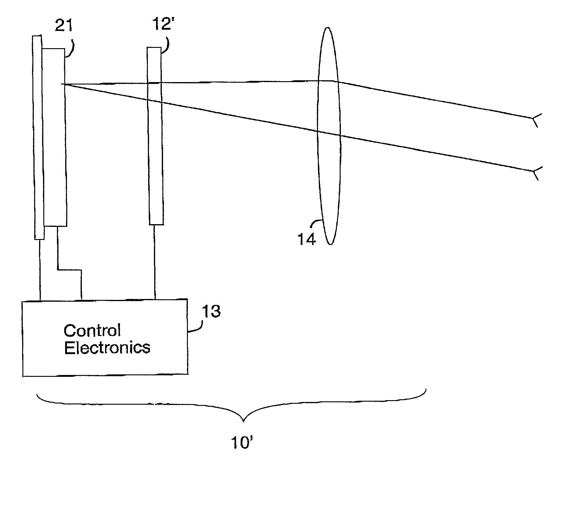
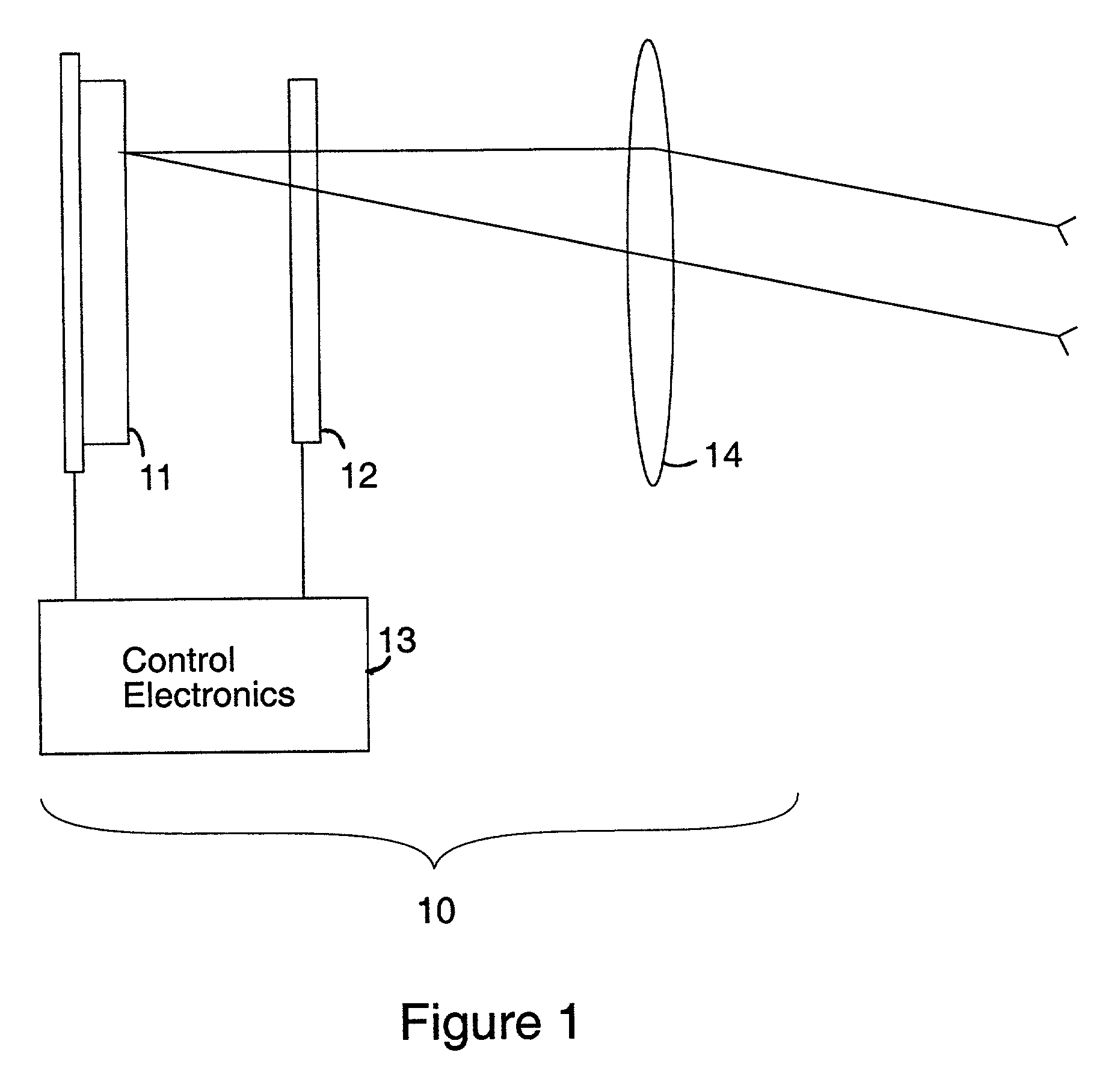
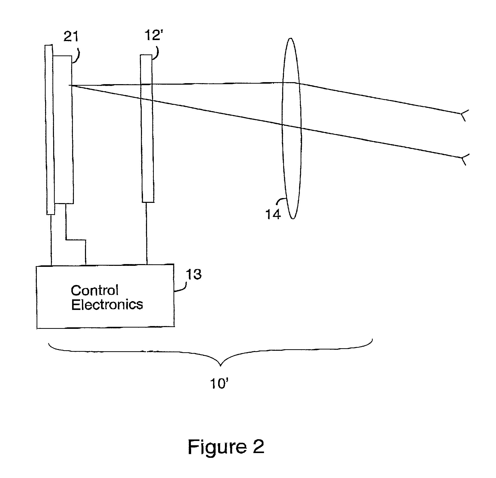
[0034] In this description, certain terms are used interchangeably. In particular, the terms "sensor" and "detector" are both used to denote a photodetector that provides at least a one-dimensional image of a scene, and more commonly, a two-dimensional image. It is specifically intended that this term include detectors comprising three photodetectors and a trichroic prism in the arrangement widely used for medical imaging and pro-level video equipment. The terms "retarder" and "waveplate" are used to denote an optical retarder that has a certain retardance which may further be described in terms of the amount of retardance. For example, a .lambda. / 2 waveplate is a retarder which exhibits an optical retardance of one half wave for light of a specified wavelength, or when no wavelength is specified, for light generally within the operating range of the system. The term "light" is used to denote visible light, infrared light, and ultraviolet light. Although the examples are drawn from ...


PUM


Abstract

The present invention provides a color imaging system and a method to capture an accurate color image by use of a tunable filter tunable between two states and a color detector that records the light transmitted through the filter when the filter is in the first state and then in the second state.

Description

[0001] 1. Field of the Invention[0002] The field relates to color imaging systems and particularly to the use of tunable filter elements together with color-sensitive detectors to provide enhanced color quality images, relative to such detectors alone.[0003] 2. Description of the Related Art[0004] The majority of all color imaging is presently performed using mosaic type detectors, where an imaging photosensor such as a charge-coupled device (CCD), charge-injection device (CID), or CMOS detector array is tiled with red, green, and blue color filters in a Bayer pattern, in stripes, or in some other regular arrangement. These sensors acquire color images, but the color rendition is not always accurate for real-world samples. This is because the spectral response of the R, G, and B channels in the camera are not exactly matched to the tristimulus functions X, Y, and Z.[0005] The latter functions represent the best known approximation to the standard human observer. Since the detector h...

Claims


Application Information

Patent Timeline
Patent Type & Authority Applications(United States)
IPC IPC(8): H04N9/04
CPCH04N2209/043H04N9/045H04N23/84
Inventor MILLER, PETER J.
Owner CAMBRIDGE RES & INSTR
Why Eureka
Try Eureka