
Method and apparatus for improving the dynamic range and accuracy of a Shack-Hartmann wavefront sensor

a dynamic range and wavefront sensor technology, applied in the field of wavefront sensing, can solve the problems of limiting the dynamic range of the wavefront sensor and erroneous position calculation

Inactive Publication Date: 2003-06-12
BAUSCH & LOMB INC
View PDF8 Cites 17 Cited by
  • Summary
  • Abstract
  • Description
  • Claims
  • Application Information

AI Technical Summary

Problems solved by technology

However, this restriction limits the dynamic range of the wavefront sensor; i.e., the maximum wavefront slope that can be measured per lenslet.
In addition, a wavefront with excessive aberrations may be incorrectly measured if some or all of the spot images are attributed to the wrong lenlets, resulting in erroneous position calculations.

Method used


Image

  • Method and apparatus for improving the dynamic range and accuracy of a Shack-Hartmann wavefront sensor
  • Method and apparatus for improving the dynamic range and accuracy of a Shack-Hartmann wavefront sensor
  • Method and apparatus for improving the dynamic range and accuracy of a Shack-Hartmann wavefront sensor

Examples


Embodiment Construction

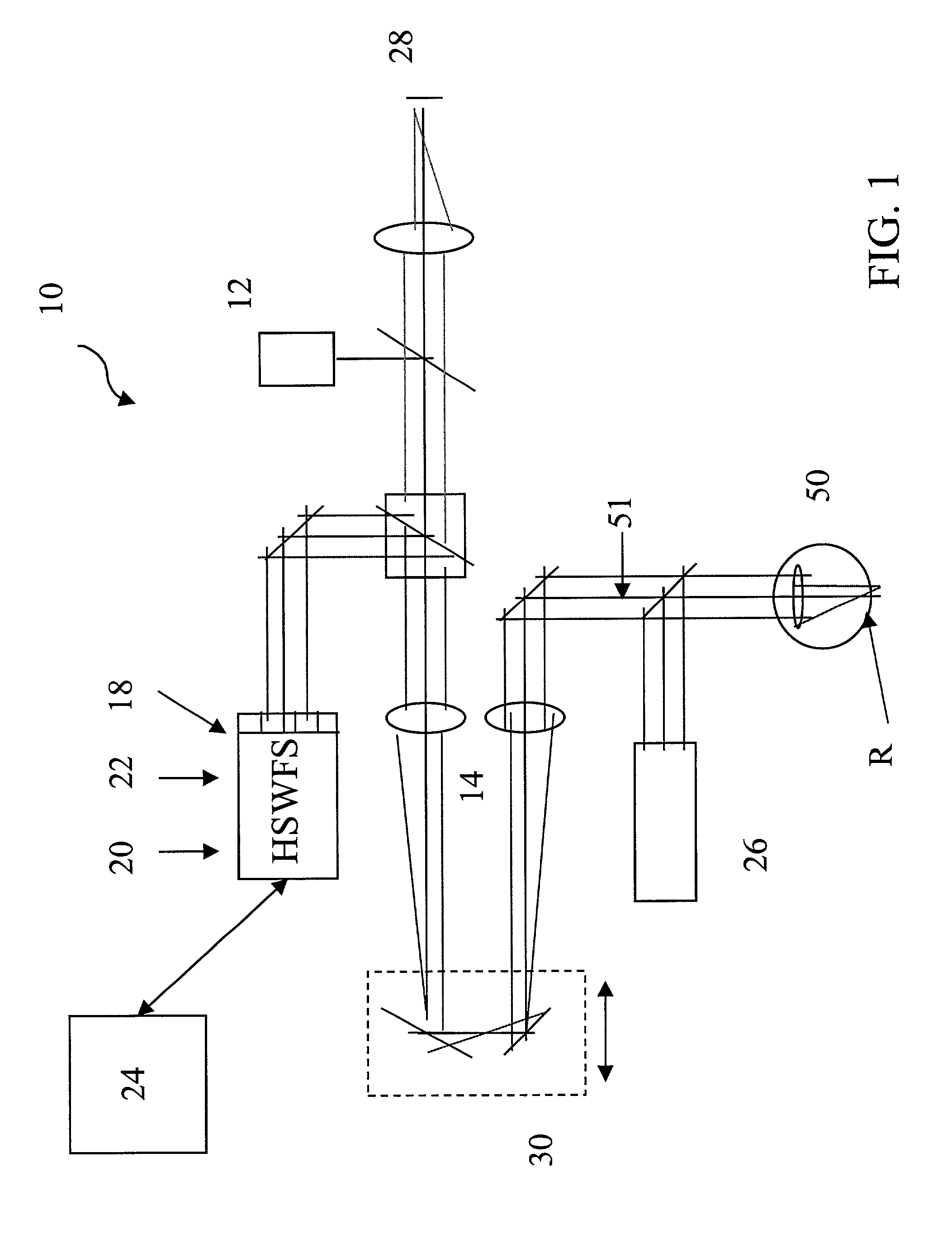
[0021] FIG. 1 shows an optical diagram of a Shack-Hartmann aberrometer 10. In general terms describing wavefront sensor operation, a patient's eye 50 is properly aligned with the measurement axis 51 of the aberrometer with the help of a fixation target 28 and an alignment camera 26, typically a pupil camera. The retina, R, of the eye is illuminated by light from a source 12 such as a 780 nm laser diode, for example, or other appropriate wavelength source, and the light is focused on the retina by an optical trombone system 30 and imaging lenses 14. The trombone system (or an alternate optical focusing system known in the art) is used to compensate for the simple near- or far-sightedness in the eye and also sharpens the focus of the image spots formed on a detector 22, resulting in more accurate wavefront measurement. The interested reader is referred to International Publication WO 01 / 28408 for a detailed description of the optical trombone system. This publication is incorporated h...


PUM


Abstract

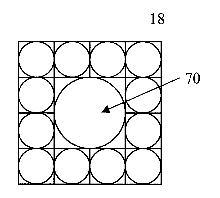
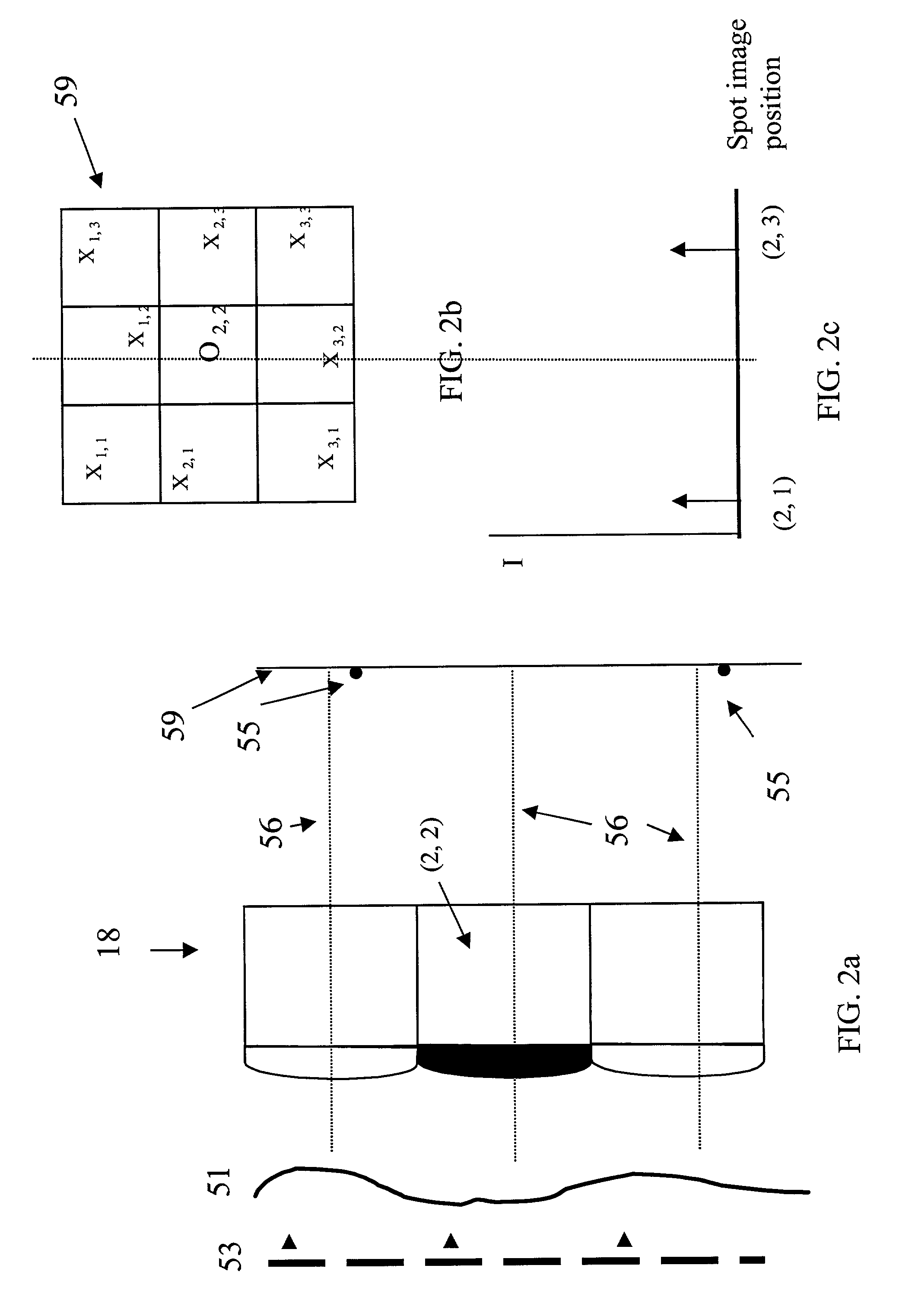
A Shack-Hartmann aberrometer for measuring ophthalmic wavefront aberrations having improved dynamic range is described. In one embodiment, a single lenslet only of the wavefront sensor microlens array is optically or physically altered. In another embodiment, a sub-array of immediately adjacent lenslets are altered. In an alternative embodiment, preferably only two non-adjacent lenslets are altered. The alteration provides for identification of the correspondence between spot images of the unknown wavefront formed by the microlens array and the respective lenslets forming the spot images. Once all the spot images are correctly identified, analysis of the incoming wavefront is simplified even when the magnitude of aberration is increased. Thus, the dynamic range and accuracy of the Shack-Hartmann aberrometer are no longer limited by the dimensions and optical properties of the lenslets.

Description

[0001] 1. Field of the Invention[0002] The present invention is directed to the field of wavefront sensing and, more particularly, to a method and apparatus for improving the dynamic range and accuracy of a Shack-Hartmann wavefront sensor.[0003] 2. Description of Related Art[0004] A typical Shack-Hartmann wavefront sensor includes, among other components, a two-dimensional array of identical positive-power lenlets (microlens array) for imaging an aberrated wavefront. Although the invention described herein is applicable to all devices that measure wavefront with a Shack-Hartmann wavefront sensor, the applications and description appearing herein will refer to a Shack-Hartmann wavefront sensor used for ophthalmic applications. However, the invention is not so limited. FIG. 1 is an optical schematic of a typical Shack-Hartmann type aberrometer. Briefly, a light source 12 illuminates a subject's eye 50 while the subject fixates on a target 28. A focus error adjusting system 30 is used ...

Claims


Application Information

Patent Timeline
Patent Type & Authority Applications(United States)
IPC IPC(8): G01J9/00
CPCG01J9/00A61B3/1015
Inventor ALTMANN, GRIFFITH E.
Owner BAUSCH & LOMB INC
Learn More