Control apparatus of internal combustion engine

a control apparatus and internal combustion engine technology, applied in the direction of electric control, ignition automatic control, speed sensing governors, etc., can solve the problems of engine torque decline, unstable fuel condition, and unstable fuel stability of the engin

Inactive Publication Date: 2003-06-26
DENSO CORP
View PDF0 Cites 30 Cited by
  • Summary
  • Abstract
  • Description
  • Claims
  • Application Information

AI Technical Summary

Problems solved by technology

If the ignition timing is retarded in order to heat the catalyst at an early time, however, the engine torque decreases.
At a cold start, however, the fuel stability of the engine is poor so that, if the ignition timing is much retarded from the cold start as is the case with the disclosed technology, the fuel condition becomes unstable, unavoidably increasing the quantity of an exhausted unburned gas component such as HC or CO.
In addition, if the ignition timing is much retarded from the cold start, the retard angle for the ignition timing causes a delay of the decreasing of the intake manifold negative pressure.
In the mean time, the negative pressure of the brake booster cannot be assured at a sufficient value so that the performance of the brake booster cannot be fully displayed.
In short, with the disclosed technology, it is difficult to assure a sufficient negative pressure of the brake booster while reducing the exhaust emission at a start of the engine at the same time.
By execution of advancing control...

Method used


Image

  • Control apparatus of internal combustion engine
  • Control apparatus of internal combustion engine
  • Control apparatus of internal combustion engine

Examples


first embodiment

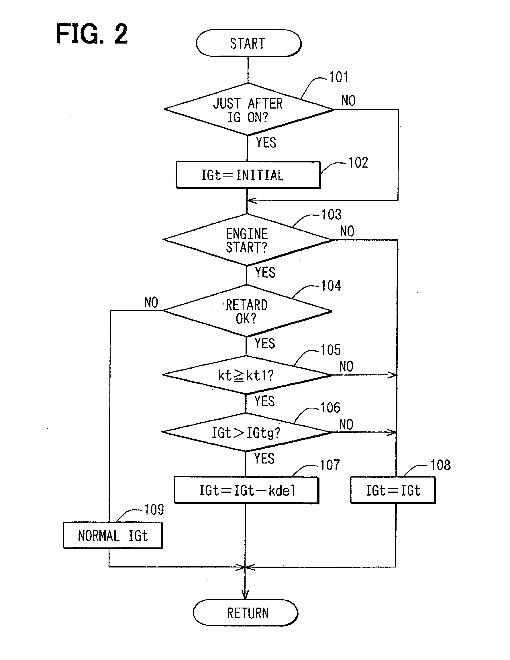
[0071] First Embodiment

[0072] A first embodiment of the present invention applied to a direct injection engine is described by referring to FIGS. 1 to 3 as follows.

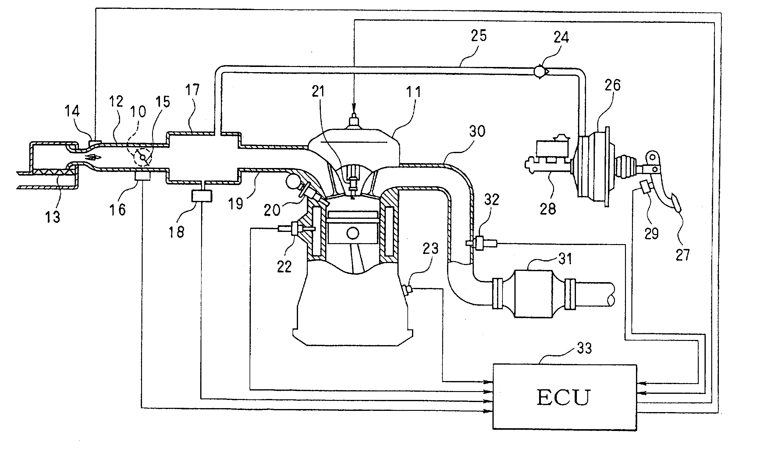
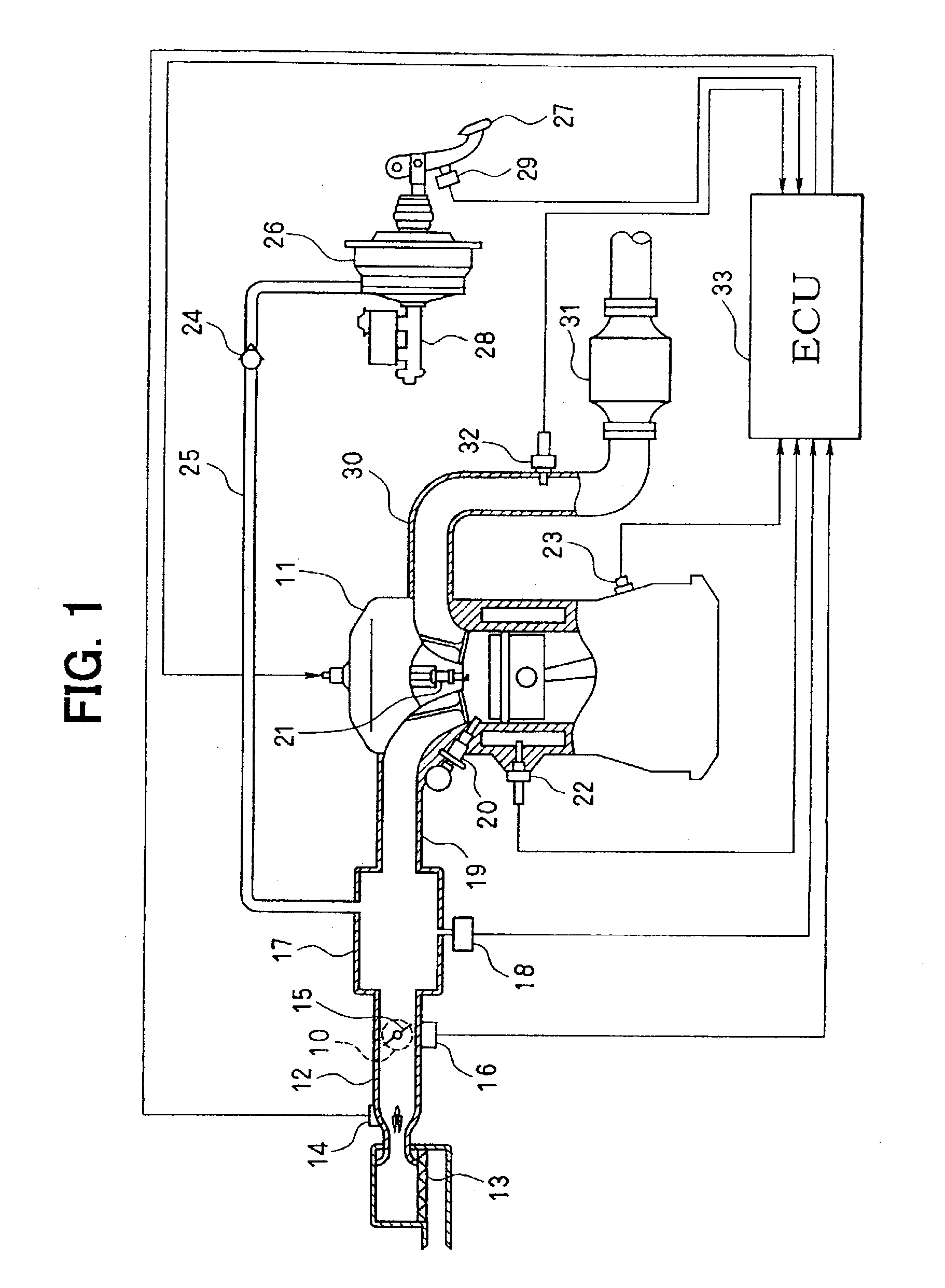
[0073] The description begins with an explanation of the entire engine control system's configuration, which is shown in FIG. 1. At the upper end of the upstream side of an intake pipe 12 employed in an engine 11 working as an internal combustion engine, an air cleaner 13 is provided. On the downstream of this air cleaner 13, an airflow meter 14 for detecting an intake airflow volume is provided. On the downstream side of the airflow meter 14, there are provided a throttle valve 15 driven by an actuator such as a motor 10 and a throttle angle sensor 16 for detecting a throttle angle.

[0074] On the downstream side of the throttle valve 15, a surge tank 17 is provided. On the surge tank 17, there is provided an intake pressure sensor 18 (negative pressure recognizing means) for detecting a negative pressure of an intake pipe...

second embodiment

[0093] Second Embodiment

[0094] In the case of the first embodiment, a timing of a state in which a proper negative pressure of the brake booster can be assured after a start of the engine is confirmed when a predetermined time lapses since the start of the engine. Such a timing is taken as a timing to start the control of retarding ignition. In the case of a second embodiment shown in FIG. 4, on the other hand, at a step 105a, an intake pipe negative pressure Pm detected by an intake pipe negative pressure sensor 18 is examined to determine whether the pressure Pm has decreased to a predetermined value kpm1 or a lower value. The predetermined value kpml is an intake pipe negative pressure at which a proper negative pressure of the brake booster can be assured. During a period between a start of the engine and a time the intake pipe negative pressure Pm decreases to the predetermined value kpm1 or a lower value, the ignition timing is sustained at an initial value instead of being re...

third embodiment

[0098] Third Embodiment

[0099] In the first and second embodiments, during a period between a start of the engine and a state in which a proper negative pressure of the brake booster can be sustained, the ignition timing is sustained at an initial value instead of being retarded. In the case of a third embodiment shown in FIGS. 5 and 6, on the other hand, during a predetermined period kt2 beginning at a start of the engine, the retardation speed of the ignition timing is lowered and, after the period, the retardation speed is increased. The period is a time it takes to lower the intake pipe negative pressure Pm to a predetermined value kpm1.

[0100] In the actual processing, at a step 103 of a flowchart shown in FIG. 5, completion of an engine start is confirmed. If the completion is confirmed, the flow of the routine goes on to a step 104 to determine whether the conditions for execution of the ignition retarding control to heat the catalyst at an early time are satisfied. If the cond...


PUM


Abstract

The ignition timing is sustained at an initial value during a predetermined time beginning at a start of an engine, and is retarded after the predetermined time is elapsed to heat a catalyst at an early time. The predetermined time ends when the negative pressure of an intake pipe or the negative pressure of a brake booster reaches to a predetermined value. That is, the predetermined time is a period, which begins at a start of the engine and ends when a proper negative pressure can be sustained in the brake booster. As a result, it is possible to assure a negative pressure in the brake booster at an early time and to reduce exhaust emission at a start of the engine simultaneously.

Description

[0001] This application is based on Japanese Patent Applications No. 2001-153412 filed on May 23, 2001, and No. 2001-223436 filed on Jul. 24, 2001 the contents of which are incorporated herein by reference.[0002] 1. Field of the Invention[0003] The present invention relates to a control apparatus of an internal combustion engine.[0004] 2. Related Art[0005] A car manufactured in recent years is provided with a catalyst such as a three-way catalyst, which is used for purifying exhausted gas, on the exhaust pipe of the car. At a cold start in which the engine is started at a low temperature of the engine and the catalyst, the ignition timing is retarded to increase the temperature of the exhausted gas. The increased temperature of the exhausted gas in turn promotes the heating of the catalyst so that the temperature of the catalyst is increased to a value in an active temperature range at an early time.[0006] If the ignition timing is retarded in order to heat the catalyst at an early ...

Claims


Application Information

Patent Timeline
IPC IPC(8): F02D13/04F02D37/02F02P5/15
CPCF02D13/04Y02T10/46F02D37/02F02D41/0255F02D41/1454F02D41/1498F02D41/187F02D2011/102F02D2041/001F02D2041/389F02D2200/0404F02D2200/0406F02D2200/0414F02D2250/41F02P5/1506F02D31/003Y02T10/40
Inventor MAJIMA, YOSHIHIROHASEGAWA, JUNYAGI, TOYOJIIIDA, HISASHI
Owner DENSO CORP
Why Eureka
Try Eureka