Biolytic filtration

a biolytic and filtration technology, applied in the field of biolytic filtration, can solve the problems of short effluent retention time, inability to increase the depth of the bed, and the treatment of wastewater by the humus matrix, so as to promote good exchange of effluent, prevent the erosion of the humus matrix, and the effect of inherent stabilisation of the surfa

Inactive Publication Date: 2003-06-26
DOWMUS PTY LTD
View PDF5 Cites 17 Cited by
  • Summary
  • Abstract
  • Description
  • Claims
  • Application Information

AI Technical Summary

Benefits of technology

0036] If effluent moves slowly through the bed in matrix flow the bed structure is less disturbed and broken down, rather the humus is trapped and accretes in the bed and forms stable aggregates through the action of living organisms in the biolytic filter ecosystem. Gentle flow has the further advantage of promoting good exchange of effluent into and out of the humus matrix.
0037] The opposite application principle of applying effluent in larger doses to deliberately produce channel flow conditions will create the effect of shedding solids from the humus matrix under those circumstances where solids shed is desired.
0038] A design principle to prevent bed buildup on its peripheral surfaces is to enable controlled erosive surface flow to occur over the surface and sides of each bed element module, but to provide sufficient protection to the surface of the bed at the intended long term surface level to prevent erosion of the humus matrix below this level. The method of providing erosive flow is to channel the peak flow of the raw effluent applied to the bed as generated over the supported humus matrix surfaces. The structural support framework can be made in such a way as to provide inherent stabilisation of the surface at a defined level much as tree roots provide protection from erosive flood flows to the soil on stream banks but allow material above the root mat to be washed away. A porous net like plastic mesh can provide this stabilisation function. Material build up above the plastic mesh layer can be eroded away and the humus matrix below it is protected somewhat. For this to be functional, the module or bed surfaces must have a controlled flow over the surfaces. This can be achieved by making the module elements with a surface that is discretely sloped. The slope is determined by the saturated infiltration rate of the humus matrix and should be great enough that when the humus matrix is saturated any further effluent applied flows off the bed in preference to forcing hydraulic flow through the larger pores in the humus matrix. Any slope which more or less achieves this objective will be acceptable. Because it is not desirable to have the excess effluent flow to a low point on the bed surface and accumulate fines through sedimentation, but rather to drain away quickly, the modules may be made with a sloping surface and base which slopes the opposite way so that the crates can fit together as a stable vertical structure by having a base module with the appropriate upper slope and a level base so that the entire stack of modules could be stacked on a level surface and produce a zig zag effluent overflow path from the discharge point to the base module. The other benefit of this sloping surface creating a flow path for the effluent is that it enables the entire surface of the humus matrix to be wet evenly by the effluent. The surface should be formed in such a way that it naturally spreads the effluent over the entire surface rather than concentrating flow. This spreading effect allows passive discharge of raw effluent onto the bed at one point to be spread evenly and at the correct dose over the entire surface of the bed.
0039] If the humus matrix volume is insufficient to absorb all of the effluent dosed onto it in an as generated effluent peak through the passive dosing means described above and so some of the effluent passes over the entire surface of the fractured bed and accumulates in a storage zone in the base, it is possible to use a small pump to mechanically dose the effluent back over the bed in optimal doses to get matrix flow through the entire bed volume and so ensure that there is maximum retention time in the bed. The dose volume must be sufficient to almost bring the humus matrix to field capacity. The doses must be timed so that air can recharge the fine pore spaces in the humus matrix between doses and so prevent anaerobic conditions developing within the humus matrix. Dosing can be controlled electronically. Ideally the controller can have logic built in to enable it to optimise the dose frequency to compensate for changing hydraulic loads through a simple level sensing arrangement in the stored effluent container Mechanical dosing may be an advantage even where the bed volume is sufficient to absorb as generated flows if higher standards of effluent are required of the effluent discharged from the system.
0040] It is sometimes desirable to remove nitrogen from effluent for environmental reasons. It has been observed in a variety of wastewater treatment applications such as denitrifying sand filters and activated sludge plants designed for nitrogen removal that biological removal of nitrogen from effluent is possible by passing effluent containing oxidised nitrogen (nitrite and nitrate) through an anoxic zone within which high dissolved carbon concentrations are found. Microbial organisms metabolise this carbon by taking oxygen from the oxidised nitrogen compounds resulting in the release of nitrogen gas, which is lost harmlessly to the atmosphere. In this way the total nitrogen in the effluent is reduced. The use of controlled dosing of effluent onto the high COD zone in or immediately below the organic solids deposition zone of the biolytic filter can be used to create nitrogen removal potential within any biolytic filter system. Recirculation of nitrified effluent has value in this context.
0041] The use of open support aggregate bed elements has been discussed above as a means of supporting humus matrix from collapse. It is important in a biolytic filter that the organisms responsible for structuring this humus matrix into a highly efficient filtration media and preserving its structure are preserved from accidental drowning through flooding. If the organisms can move upward faster than the rate of water level rise they will concentrate on the surface of the bed. The open support aggregate structured bed allows for this upward migration of adult organisms. Stable humus matrix with little air entrained is slightly heavier than water and will be submerged by rising water. The surface layers are sometimes naturally buoyant dependent on the amount of paper and other such fibrous material added to the bed as organic solids and the amount of air entrained. Sometimes this phenomenon naturally preserves many invertebrates in the event of flooding, but not always. It is proposed that the open support aggregate structured bed elements be made using durable buoyant plastic or foams as the humus matrix support lattice material so that in the event of flooding the upper portion of a random media fractured bed could form a stable life raft for an indefinite period where a buried container can not be provided with an emergency overflow drain below the surface of the bed.

Problems solved by technology

One of the limitations of the aforementioned biolytic filtration protocol is that the surface area of the bed determines the amount of wastewater that can be regularly applied over a long period of time, and the amount of treatment possible is dependent upon the depth and volume of the bed and the hydraulic retention time in the bed.
The depth of the bed however cannot be increased beyond a certain limit without the lower layers of the bed being crushed by the weight of the bed itself and the pore spaces destroyed so that blockage can result.
A second limitation is that the surface layer of the bed is by far the most biologically active and diverse zone where the most rapid biolysis takes place.
The surface area of the biolytic filter bed container therefore limits the amount of wastewater or high solids slurry that can be applied to the biolytic filter bed, and the failure mode is related to the capacity of air and water to penetrate into the bed.
A third limitation is that the treatment of wastewater by the humus matrix, which requires removal of dissolved and suspended organic material, is compromised when typical flow peaks are applied to the bed as they create channel flow through the bed which erodes the bed so adding suspended solids to the filtrate and results in short effluent retention times.
A fourth limitation of the biolytic filter is that the biological activity in the system is vulnerable to flooding or prolonged inundation.
If the adult population of the living organisms in the system are drowned, the population takes several weeks to recover and may need re-inoculating.
This could be a logistical problem and considerable expense in a remote installation.

Method used


Image

  • Biolytic filtration
  • Biolytic filtration

Examples


Embodiment Construction

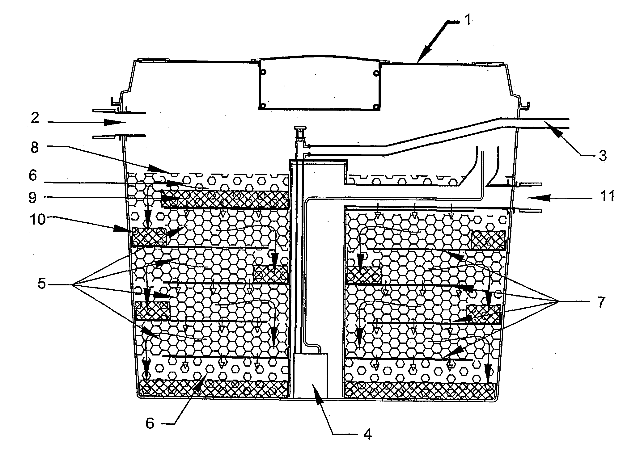
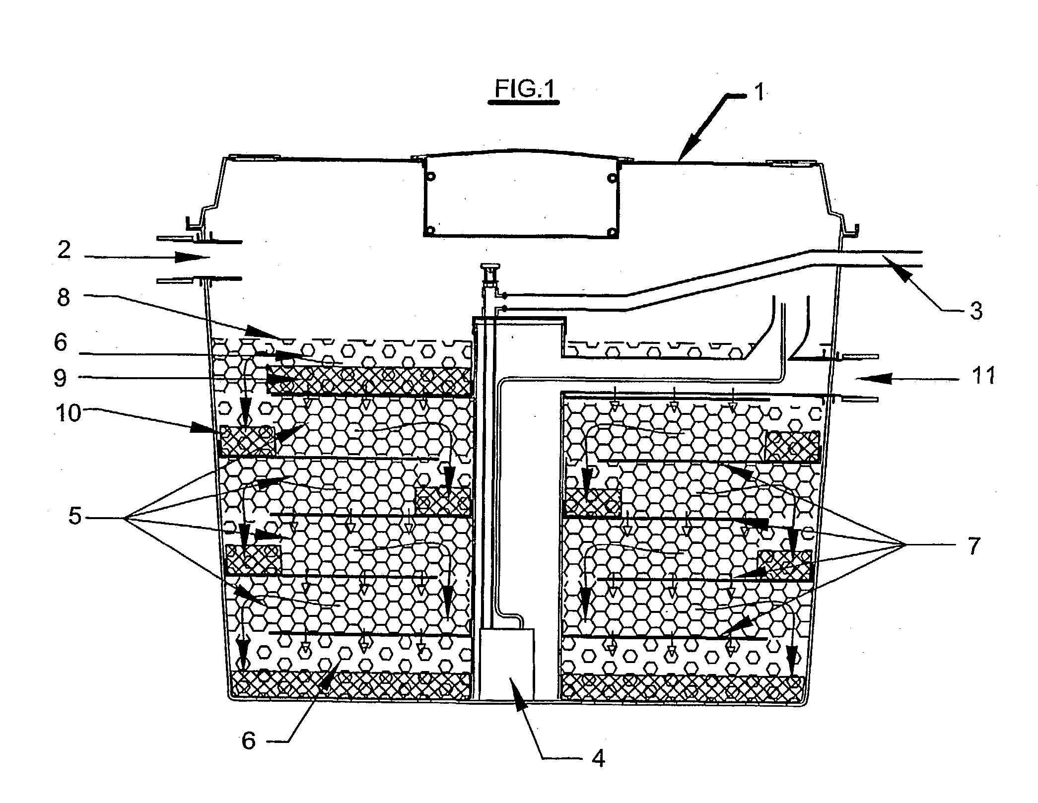
[0043] Referring to the drawing, the humus matrix support lattice structured bed biolytic filter comprises a conventional septic tank 1 with effluent inlet 2 and filtrate outlet 3. A submersible pump 4 is located in a sump in the base zone of the tank and an overflow duct is located in an upper region 11.

[0044] The tank contains support lattice bed elements of two types. Humus matrix elements 5, to provide long retention and filtration of effluent, and drainage matrix elements 6 to provide drainage, upper bed support and aeration. These elements 5, 6, are formed by cutting flexible corrugated plastic drainage pipe and bagging it in open mesh bags either with a humus like substitute such as peat (humus matrix elements) or without (drainage matrix elements).

[0045] Drainage bed elements 6 are formed into a layer in the base of the tank, with several humus matrix layers 5 above it, each placed over a geotextile flow barrier 7 designed to reduce channel flow, trap suspended solids, and i...


PUM

PropertyMeasurementUnit
pore sizeaaaaaaaaaa
surface areaaaaaaaaaaa
volumeaaaaaaaaaa

Abstract

A filtration bed support for biolytic filtration wherein the filtration bed comprises a bed of solids in various stages of decomposition ranging from raw unprocessed organic material on the surface of the bed to fully decomposed humus which forms the bulk of the bed. The bed is kept from blocking by living organisms. The support comprises a three dimensional humus matrix lattice.

Description

[0001] This invention relates to an improved biolytic filtration protocol for wastewater and solid organic waste material, and is particularly concerned with the use of a structural framework to facilitate such filtration protocol.[0002] The type of biolytic filtration with which the present invention is concerned, is the subject of a portfolio of patents held by the applicant and which is typified by U.S. Pat. No. 5,633,163. The biolytic filtration consists of the simultaneous treatment of wastewater and solid organic waste material on a bed of solids in various stages of decomposition ranging from raw unprocessed organic material added to the surface of the bed, through to fully decomposed humus which is a very active filtration matrix and which forms the bulk of the bed. The bed is kept from blocking through the action of a farm of living organisms selected from worms, insects, crustaceans, mites and the like which create pores throughout the filtration matrix. The humus matrix c...

Claims


Application Information

Patent Timeline
Patent Type & Authority Applications(United States)
IPC IPC(8): C02F3/04C02F3/10C05F17/00C05F17/02
CPCC02F3/04C02F3/10C05F17/0205C05F17/0018C02F11/16Y02P20/145C05F17/40C05F17/907Y02W30/40Y02W10/10
Inventor CAMERON, DEAN OSMAN
Owner DOWMUS PTY LTD
Why Eureka
Try Eureka