Anisotropic etching method and apparatus

a technology of anisotropic etching and etching depth, which is applied in the direction of basic electric elements, electrical equipment, semiconductor/solid-state device manufacturing, etc., can solve the problems of unstable anisotropic etching, inability to perform stable anisotropic etching, and uneven etching depth, etc., to achieve the effect of improving anisotropic etching

Inactive Publication Date: 2003-07-03
MITSUBISHI MATERIALS SILICON CORP
View PDF7 Cites 6 Cited by
  • Summary
  • Abstract
  • Description
  • Claims
  • Application Information

AI Technical Summary

Benefits of technology

0027] It is an objective of the present invention to provide an anisotropic etching method and apparatus for solving the above-explained problems and improving the anisotropic etching.

Problems solved by technology

ccordingly, there occurs a problem in that the etching characteristics differ for each wafer case which contains a plurality of silicon wafers. I
Therefore, as shown in the graph of FIG. 7 which shows the relationship between the replenishment timing and variations in the etching state, the temperature of the anisotropic etchant decreases every time the vessel is replenished, so that stable anisotropic etching cannot be performed.
Another problem also occurs in the conventional technique, in that the etching depth may not be uniform.
As a result, after the quartz heater 102 is used for a long time, a hole is formed in the quartz tube 102a, and as a result, the anisotropic etchant may be contaminated.
Another problem also occurs.
Therefore, if a spark occurs at a contact in the electric wiring of the quartz heater 101, the evaporated IPA may catch fire.
In addition, when such a heater put into the vessel is used, it is difficult to keep a uniform temperature distribution in the liquid in the vessel.
However, also in this case, it is impossible to prevent the contamination of the etchant caused by pin holes, or to prevent the evaporated IPA component from catching fire due to sparks.
In this case, there occurs a problem in that the efficiency of heating the anisotropic etchant in the vessel is relatively low.
However, also in this case, a problem similar to that caused by the hot plate 201 occurs.
Therefore, the composition of the anisotropic etchant may not stay in a suitable range.
Even if it is assumed that a portion of the upper layer, that is, the IPA-rich portion "a" is drawn, a similar problem occurs.
In addition, if it is assumed that a portion of the IPA-rich portion "a" and a portion of the KOH-rich portion "b" are simultaneously drawn, then another problem may occur in which it is difficult to balance the absorption between the IPA-rich etchant and the KOH-rich etchant.

Method used


Image

  • Anisotropic etching method and apparatus
  • Anisotropic etching method and apparatus
  • Anisotropic etching method and apparatus

Examples


first embodiment

[0092] First Embodiment

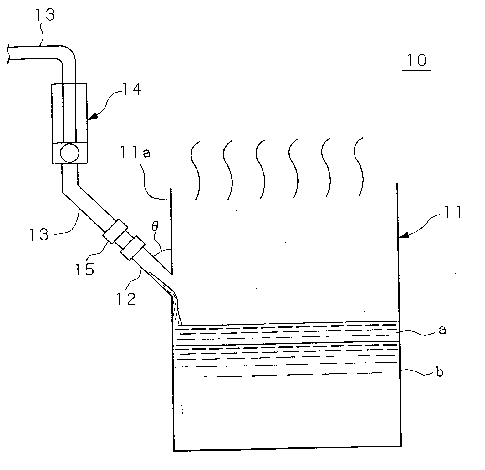
[0093] FIG. 1 is a perspective view showing the anisotropic etching apparatus of the first embodiment.

[0094] In FIG. 1, reference numeral 10 indicates the anisotropic etching apparatus of the present embodiment. This anisotropic etching apparatus 10 comprises an anisotropic etching vessel 11 and an evaporated component compensating unit 14 (i.e., evaporated component compensating device) which is attached to a center area of a side plate 11a of the vessel 11 via a replenishing nozzle 12 and a replenishing pipe 13.

[0095] The anisotropic etching vessel 11 is made of a quartz glass and has a cubical shape, and has chemical resistance to a three component anisotropic etchant of IPA / KOH / H.sub.2O. The volume of the vessel is 20 L, and the top of the vessel is open, that is, the vessel has an open top area.

[0096] A wafer case containing a plurality of silicon wafers (not shown) is immersed in the anisotropic etchant through the open area. The anisotropic etchant is s...

second embodiment

[0111] Second Embodiment

[0112] FIG. 4 is a diagram for explaining the anisotropic etching apparatus of the second embodiment according to the present invention.

[0113] In FIG. 4, reference numeral 1010 indicates the anisotropic etching apparatus of the second embodiment. This anisotropic etching apparatus 1010 comprises (i) a circular anisotropic etching vessel 1011, (ii) a heating medium jacket 1012 which surrounds the outer peripheral face of the vessel 1011 and contains hot and pure water (i.e., a heating medium) for indirectly heating the anisotropic etchant in the vessel, (iii) an ultrasonic vibrator 1013 (functioning as an agitating device), attached to the bottom of the anisotropic etching vessel 1011, for indirectly agitating the anisotropic etchant in the vessel, (iv) a heating medium circulating passage 1014, both ends of which are respectively joined with the heating medium jacket 1012, for drawing and guiding the hot and pure water from the anisotropic etching vessel 1011...

third embodiment

[0126] Third Embodiment

[0127] The anisotropic etching apparatus as the third embodiment according to the present invention will be explained with reference to FIG. 5. FIG. 5 is a diagram for explaining the structure of the anisotropic etching apparatus of the third embodiment.

[0128] In FIG. 5, reference numeral 1020 indicates the anisotropic etching apparatus of the third embodiment. In the apparatus 1020, the ultrasonic vibrator 1013 used in the second embodiment is omitted, and in place of the heating medium jacket 1012, another type of heating medium jacket 1012 is provided, which surrounds the peripheral side face and bottom of the anisotropic etching vessel 1011.

[0129] The third embodiment employs the heating medium jacket 1012 having the above shape; thus, the efficiency of heating the anisotropic etchant by using the hot and pure water can be improved.

[0130] The structure, function, and effect related to each of the other elements are the same as those of the second embodimen...


PUM

PropertyMeasurementUnit
boiling pointaaaaaaaaaa
temperatureaaaaaaaaaa

Abstract

An anisotropic etching method and apparatus is disclosed, by which the anisotropic etching of a wafer surface can be stably performed, the generation of mu pyramids generated on the etched surface of a semiconductor wafer can be reduced, and the etching depth can be uniform. Therefore, during the anisotropic etching, a replenishing etchant which compensates for the evaporation of a component from the surface of the anisotropic etchant is continuously supplied by an amount corresponding to the amount of the component evaporated. An anisotropic etching apparatus is also disclosed, by which the etchant is not contaminated, the evaporated component of the etchant does not catch fire, the composition of the etchant does not change and the characteristics of the anisotropic etching are stabilized, the generation of mu pyramids can be suppressed, and the etching depth is uniform over the wafer surface. In the apparatus, when a circulating pump is operated, a heating medium in a heating medium jacket is drawn into a heating medium circulating passage, and then is heated by a heating device in the middle of the passage and returned to the jacket. The anisotropic etchant in the anisotropic etching vessel is heated by the heat of the returned heating medium.

Description

[0001] The present invention relates to an anisotropic etching method and apparatus. More specifically, the present invention relates to an anisotropic etching method and apparatus for preventing the evaporation of a volatile component of an anisotropic etchant due to heat generated in the etching, which changes the composition of the etchant. The present invention also relates to an anisotropic etching apparatus in which the anisotropic etchant is not contaminated, and an evaporated component of the anisotropic etchant does not catch fire at the heat source, thereby obtaining preferable etching characteristics and suppressing the generation of .mu. pyramids on an etching surface of a wafer.[0002] The dielectric separative wafer is known as a kind of semiconductor wafer. In order to form a dielectric separative wafer, (i) grooves (for dielectric separation) are formed on the surface of a silicon wafer, (ii) an oxide film (i.e., insulating film) is formed on the wafer, (iii) a polysi...

Claims


Application Information

Patent Timeline
Patent Type & Authority Applications(United States)
IPC IPC(8): H01L21/00H01L21/306
CPCH01L21/67086H01L21/30608
Inventor OI, HIROYUKI
Owner MITSUBISHI MATERIALS SILICON CORP
Why Eureka
Try Eureka