Sensor cover and method of construction thereof

Inactive Publication Date: 2003-07-10
VEONEER US LLC
View PDF0 Cites 24 Cited by
  • Summary
  • Abstract
  • Description
  • Claims
  • Application Information

AI Technical Summary

Benefits of technology

0006] The present invention overcomes the disadvantages described above of known sensor covers. An aspect of this invention is to form a high frequency electromagnetic wave transparent cover that can be designed as a decorative structure, such as a logo or manufacturer nameplate, or as any vehicle component, such as a grill. The cover i

Problems solved by technology

However, the customary materials that are used for exterior vehicular shells, namely metals, are not transparent to the high frequency waves, including radar waves.
A disadvantage of this type of cover is that the

Method used


Image

  • Sensor cover and method of construction thereof
  • Sensor cover and method of construction thereof
  • Sensor cover and method of construction thereof

Examples


Embodiment Construction

[0018] The following description of the preferred embodiment of the invention is not intended to limit the invention to this preferred embodiment, but rather to enable any person skilled in the art of high frequency sensor coverings to make and use this invention.

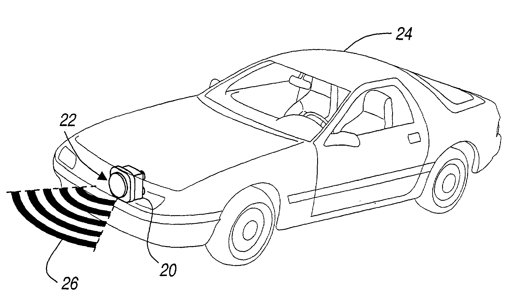
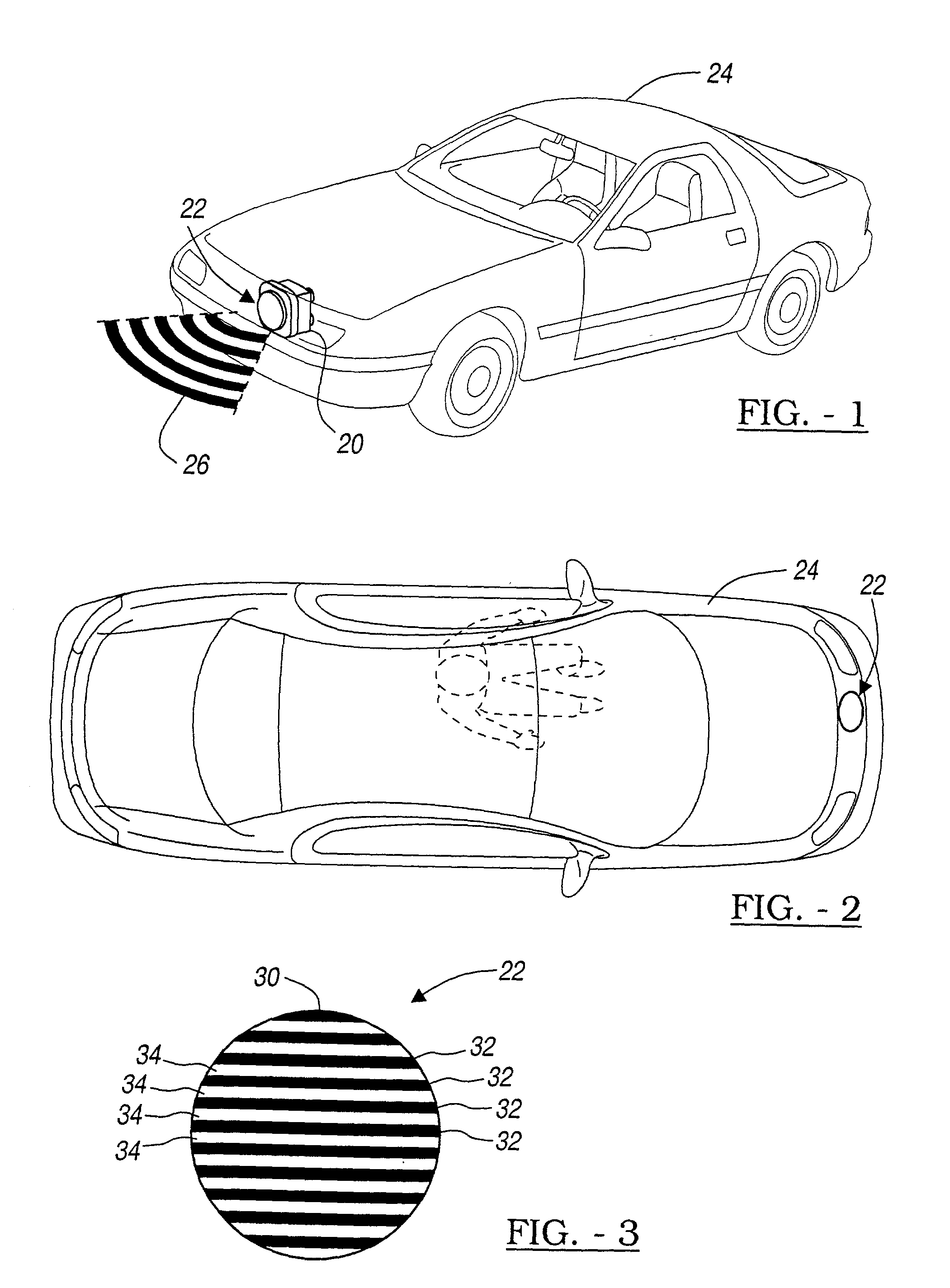
[0019] The high frequency sensor covering is used to camouflage a high frequency sensor, for example, a radar sensor. The high frequency sensor is capable of transmitting and receiving sensor signals. As shown in FIG. 1, the radar sensor 20 and cover, shown generally at 22, can be mounted to a vehicle 24, although it is important to note that this invention is not limited to sensors and coverings used in association with vehicles. The radar sensor 20 and cover 20 are shown mounted in the front region of the vehicle 24 in FIG. 1, however, this invention includes sensors and covers that are mounted at any position on the vehicle.

[0020] The cover 22 masks the location of the sensor 20 yet allows the radar signals 26 to pass th...


PUM


Abstract

A sensor cover is disclosed for camouflaging a high frequency sensor, including for example, a radar sensor. The sensor cover includes a substrate having a non-planar surface with non-signal transmitting regions and signal transmitting regions. A metal layer is disposed on each of the non-signal transmitting regions. Further, each of the non-signal transmitting regions is separated by one of the signal transmitting regions. The method of constructing such a sensor cover is also disclosed.

Description

TECHNICAL FIELD[0001] The present invention relates generally to a radar sensor cover and, more specifically, to a sensor cover that allows minimal radar signal attenuation and minimal radiation pattern distortion.BACKGROUND[0002] The use of high frequency sensors in automotive detection and control systems is becoming more prevalent. One type of high frequency sensor frequently used in vehicular applications is a radar sensor. For example, adaptive cruise control (ACC) systems utilize a radar sensor to control the speed and distance of a vehicle equipped with an ACC system and a target vehicle. For aesthetic purposes, it is advantageous to hide the sensor components from view. However, the customary materials that are used for exterior vehicular shells, namely metals, are not transparent to the high frequency waves, including radar waves.[0003] There are several prior art cover designs that are used to hide or camouflage the sensor components. One known cover design is made from an...

Claims


Application Information

Patent Timeline
IPC IPC(8): H01Q1/40
CPCH01Q1/405
Inventor RAHAIM, SAMUEL G.GORDON, ROBERT JOSEPHZORATTI, PAUL KIRKTIERNAN, TIMOTHY ARTHURBELKE, ROBERT EDWARD
Owner VEONEER US LLC
Why Eureka
Try Eureka