Method and control circuitry for a three-phase three-level boost-type rectifier

a three-level boost and rectifier technology, applied in the field of electric rectifiers, can solve the problems of increasing utility pollution, large overvoltage, and additional harmonic losses, and achieve the effects of reducing input current, reducing the quality of waveform generation, and simplifying analysis

a three-level boost and rectifier technology, applied in the field of electric rectifiers, can solve the problems of increasing utility pollution, large overvoltage, and additional harmonic losses, and achieve the effects of reducing input current, reducing the quality of waveform generation, and simplifying analysis

US20030128563A1Inactive Publication Date: 2003-07-10VERTIV CORP

Image

  • Method and control circuitry for a three-phase three-level boost-type rectifier
  • Method and control circuitry for a three-phase three-level boost-type rectifier
  • Method and control circuitry for a three-phase three-level boost-type rectifier

Examples


Embodiment Construction

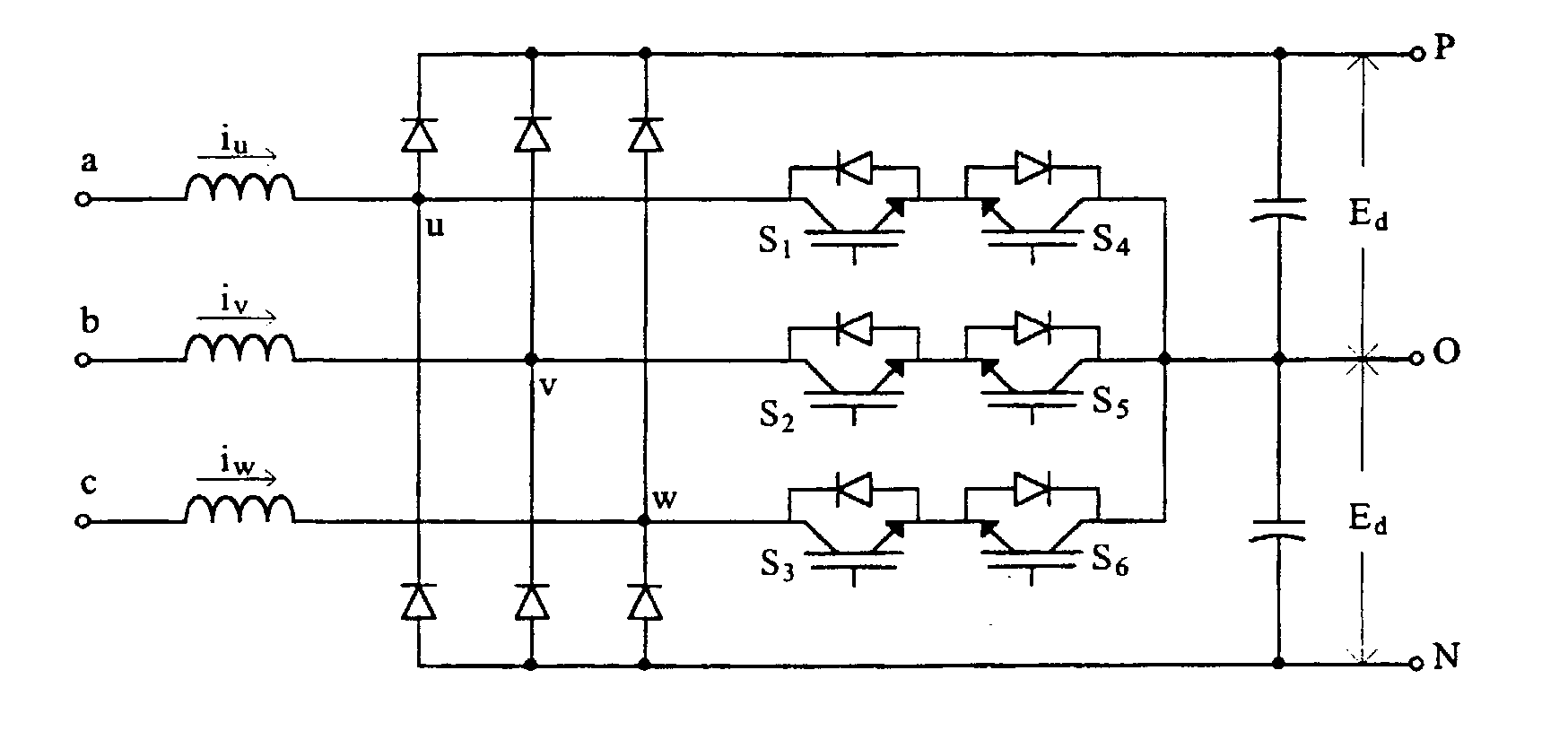
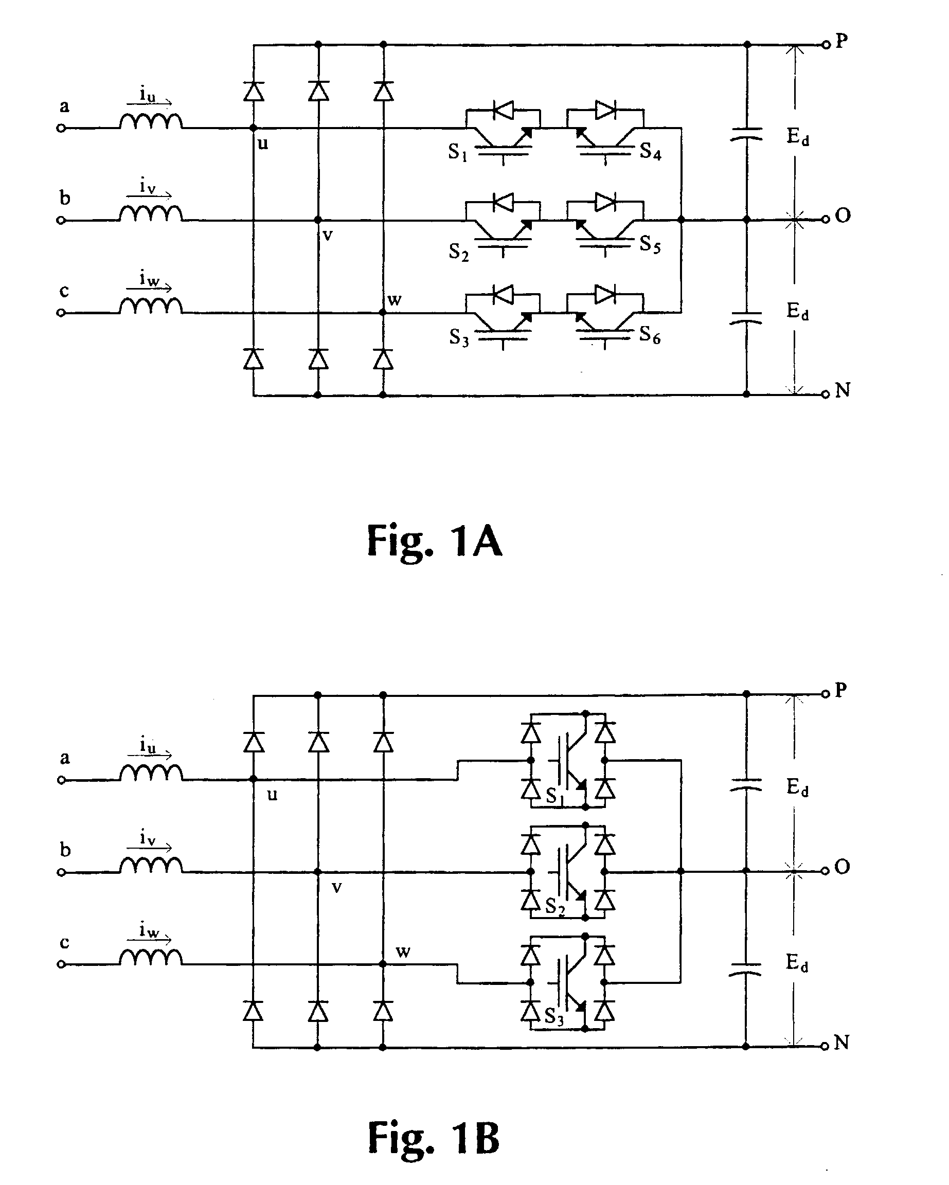
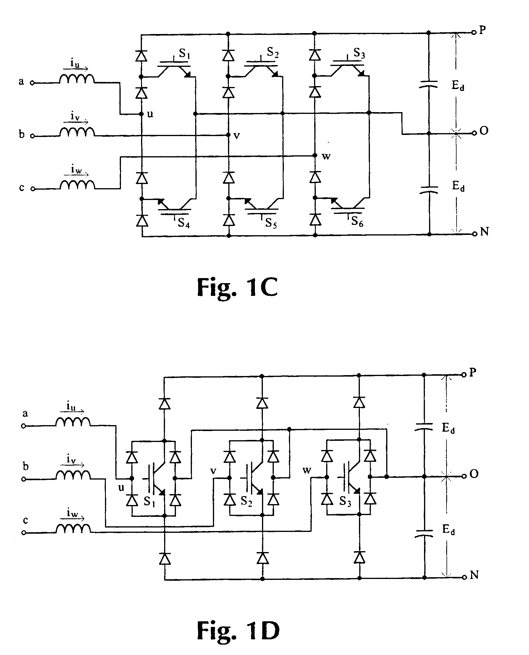
[0086] The achievements of the proposed control method will now be described in greater detail. The items considered are: controllability of the output voltage, switching frequency variations, input terminals voltage waveform, input current ripple, neutral potential balance, control circuit simplicity and feasibility demonstrated by simulation and experimental results. It is important to remark that the proposed control method keeps the advantageous characteristics of the three-phase three-level boost-type rectifiers such as:

[0087] Low voltage stress on the switching devices. Since the blocking voltage is only half the total DC-link, it allows the use of power switches with better higher switching frequency capability, smaller voltage drop when conducting and cheaper price.

[0088] There is no possibility of shot-though current on the rectifier arm; and therefore the gating of the switches is simplified and the circuit becomes more robust in operation.

[0089] Generates two output volta...


PUM


Abstract

A synchronized control method for a three-phase three-level boost-type rectifier with reduced input current ripple and balanced output voltages is disclosed. The proposed control allows simplifying the control circuit as much as possible without compromising the rectifier performance. In fact, besides simplicity, the control method featured synchronized command signals to de switching devices, minimized input current ripple, full controllability of the output voltage, dynamic balance of the output center point, constant switching frequency, simplified design of EMC filters, good transient and steady state performance, and low cost. The invention described first the most important configurations that the three-phase three-level boost-type rectifier may assume and studied the converter's operation. The concept involved for output voltage, input current, neutral point balance and control system design was presented.

Description

I--TECHNICAL BACKGROUND[0001] 1--Technical Field[0002] The present invention is related to the electrical rectifier field, more specifically, to the field of control techniques for the three-phase three-level boost type rectifier.[0003] This work introduces a new control method and control circuit for a three-phase three-level boost-type rectifier. Under the proposed control method and control circuit, the rectifier performs three-phase AC-DC conversion generating sinusoidal input currents with reduced ripple and near unity power factor while balancing the two DC output voltages. The control circuit uses two triangular carriers with the same amplitude but 180 degrees phase-shifted; Trg1 is used during the positive halve cycle and Trg2 for the negative one. The advance of the method is that the switching pulses are synchronized and appropriately distributed, allowing the reduction of the input current ripple. An effective balance of the output voltage is obtained by adding a sensor t...

Claims


Application Information

Patent Timeline
10 Jul 2003
Publication
US20030128563A1
IPC
H02M1/00; H02M1/42
CPC
H02M1/4216; H02M7/487; Y02B70/126; Y02B70/10
Inventors
ROJAS ROMERO, MANUEL ROBERTO