

Cutting tip for rotating cutting tool and rotating cutting tool using the tip, and method of machining using the tool
a cutting tool and cutting tool technology, applied in the direction of turning machine accessories, shaping cutters, manufacturing tools, etc., can solve the problems of small unevenness of cutting edge ridges, increase production costs, and inability to inhibit the development of burrs using pcd, so as to improve the smoothness of the surface, improve the roughness of the bottom surface, and reduce the unevenness of the finished surface
Inactive Publication Date: 2003-07-17
SUMITOMO ELECTRIC IND LTD
View PDF7 Cites 30 Cited by
- Summary
- Abstract
- Description
- Claims
- Application Information
AI Technical Summary
Benefits of technology
0004] As described above, the rotating cutting tool holding inserts whose cutting edges are made of PCD has mainly been used for milling such as aluminum die casting alloy, because PCD possesses appropriate hardness and toughness. In particular, a wiper insert with an arc shaped cutting edge is often used to improve the bottom surface roughness in the finishing machining process. When an arc
Problems solved by technology
The development of burrs causes an increase in the manufacturing process to remove the burrs and an increase in the production cost.
Therefore it is impossible to inhibit the development of burrs using PCD.
Therefore small unevenness of the ridges at the cutting edge is required to machine a smooth finished surface.
However since P
Method used
View moreImage
Smart ImageViewing Examples

Examples
 PUM
| Property | Measurement | Unit |
|---|---|---|
| Length | aaaaa | aaaaa |
| Length | aaaaa | aaaaa |
| Radius | aaaaa | aaaaa |
Abstract
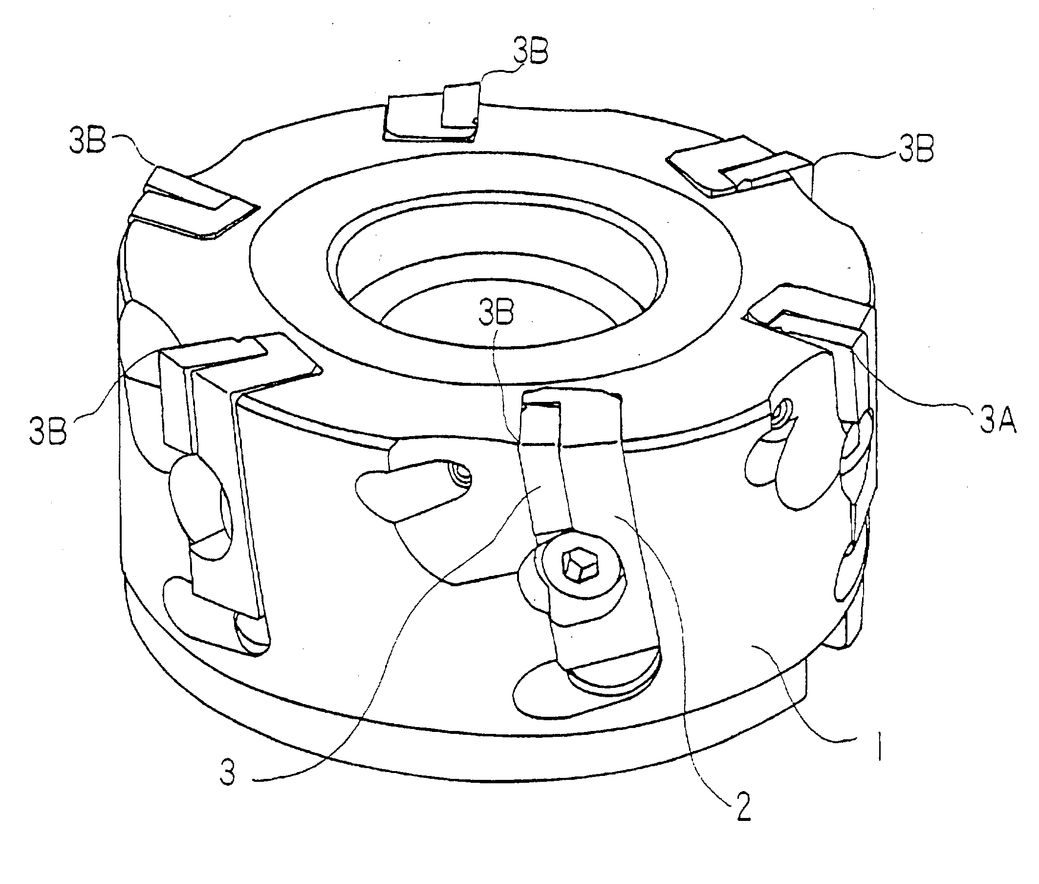
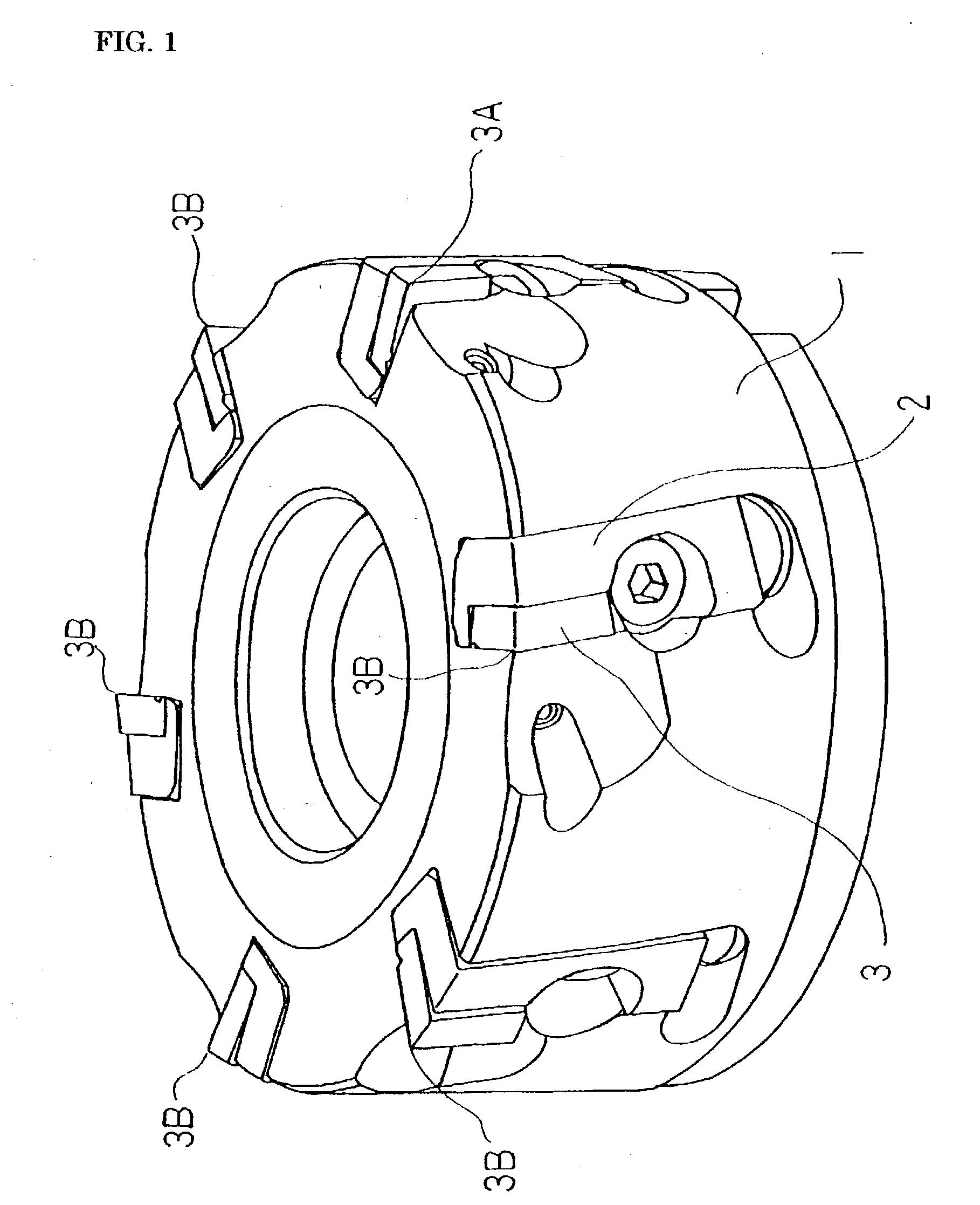
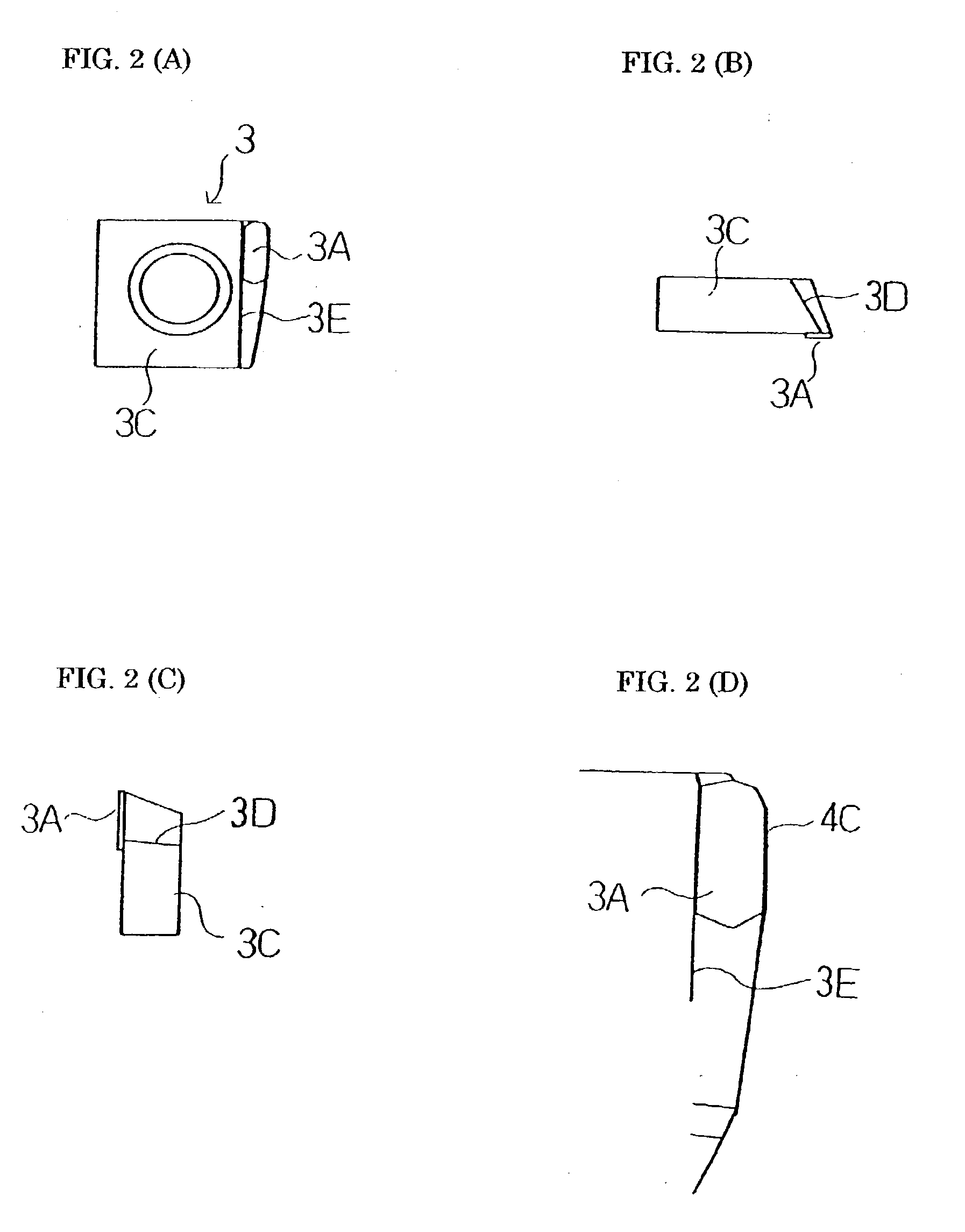
The present invention provides a cutting insert, a rotating cutting tool holding said cutting insert and a cutting method using the tool which is able to prevent the occurrence of burrs and to cut a smooth finished surface. In a rotating cutting tool which carries a plurality of cutting inserts, at least one insert is made of single crystal diamond 3A, and the minor cutting edge of the insert has an arc shaped portion whose radius is in the range of 10 mm or more to 500 mm or less. A high hard material other than single crystal diamond, for example PCD 3B, is used for the remainder of the cutting inserts. It is preferable that a cutting edge of single crystal diamond 3A be projected to the rotating axis direction in the range of 0.01 mm or more to 0.05 mm or less, compared with the cutting edges of high hard material.
Description
[0001] The invention pertains to an insert for a rotating cutting tool, a rotating cutting tool and cutting method using the rotating cutting tool that provide improved performance features for non ferrous metals such as aluminum cast alloys.[0002] A sintered diamond body (PCD) tool has been widely used in cutting non ferrous metal, especially aluminum alloy for automotive parts and electronics parts. For example as shown in FIG. 1 a face milling cutter having a ring shaped body 1 which holds a plurality of locating pieces, each locating piece carrying an insert 3 is well known. Almost all of an insert 3 is composed of cemented carbide and PCD is only used at the cutting edge. All the cutting edges of the insert 3 are made of PCD.[0003] A cutting edge of an insert has an ordinary wiping edge (the first minor cutting edge), and each insert is held by a means of uniform projection to the rotating axis direction. When a high accurate finished surface is required, a face milling cutter ...
Claims
Login to View More Application Information
Patent Timeline
 IPC IPC(8): B23B27/14B23B27/20B23C5/00B23C5/06B23C5/20B23C5/22
CPCB23C5/00Y10T407/192B23C5/2226B23C2200/201B23C2200/203B23C2200/283B23C2210/285B23C2210/287B23C2210/325B23C2220/44B23C2220/605B23C2222/04B23C2226/31B23C2226/315B23C2228/04Y10T409/303808Y10T407/1924Y10T407/23B23C5/207B23C5/202
InventorKURODA, YOSHIHIROJOJI, UEDATOSHIYUKI, SAHASHIMIKI, YOSHINAGAKAZUSHI, OBATAHIRONOBU, MAKI
OwnerSUMITOMO ELECTRIC IND LTD