Physiological sample collection devices and methods of using the same

a collection device and physiological technology, applied in the field of physiological sample collection, can solve the problems of difficult use or high manufacturing cost, difficult to obtain sample, cumbersome and complicated devices, etc., and achieve the effect of great repeatability

Inactive Publication Date: 2003-07-31
LIFESCAN INC
View PDF33 Cites 395 Cited by
  • Summary
  • Abstract
  • Description
  • Claims
  • Application Information

AI Technical Summary

Benefits of technology

0017] The present invention further includes methods for fabricating the subject test strip devices, in which a microneedle or skin-piercing element is fabricated as an integral part of a biosensor having a test strip configuration. Such devices have wholly integrated functions including accessing the physiological fluid within the skin, extracting such fluid, transferring the fluid to a measurement area and providing the components necessary for the measurement of analyte concentration in the sample. In addition to fabricating wholly integrated test strip devices, the subject fabrication methods are ideal for the fabrication of such devices which hav

Problems solved by technology

Obtaining the sample often involves cumbersome and complicated devices which may not be easy to use or may be costly to manufacture.
Furthermore, the procedure for obtaining the sample may be painful.
For example, pain is often associated with the size of the needle used to obtain the physiological sample and the depth to which the needle is inserted.
Because of these disadvantages, it is not uncommon for patients who require frequent monitoring of an analyte to simply become non-compliant in monitoring themselves.
With diabetics, for example, the failure to measure their glucose level on a prescribed basis results in a lack of information necessary to properly control the level of

Method used


Image

  • Physiological sample collection devices and methods of using the same
  • Physiological sample collection devices and methods of using the same
  • Physiological sample collection devices and methods of using the same

Examples


Embodiment Construction

[0030] Before the present invention is described, it is to be understood that this invention is not limited to the particular embodiments described, as such may, of course, vary. It is also to be understood that the terminology used herein is for the purpose of describing particular embodiments only, and is not intended to be limiting, since the scope of the present invention will be limited only by the appended claims.

[0031] Where a range of values is provided, it is understood that each intervening value, to the tenth of the unit of the lower limit unless the context clearly dictates otherwise, between the upper and lower limit of that range and any other stated or intervening value in that stated range is encompassed within the invention. The upper and lower limits of these smaller ranges may independently be included in the smaller ranges is also encompassed within the invention, subject to any specifically excluded limit in the stated range. Where the stated range includes one ...


PUM

PropertyMeasurementUnit
Fractionaaaaaaaaaa
Fractionaaaaaaaaaa
Fractionaaaaaaaaaa

Abstract

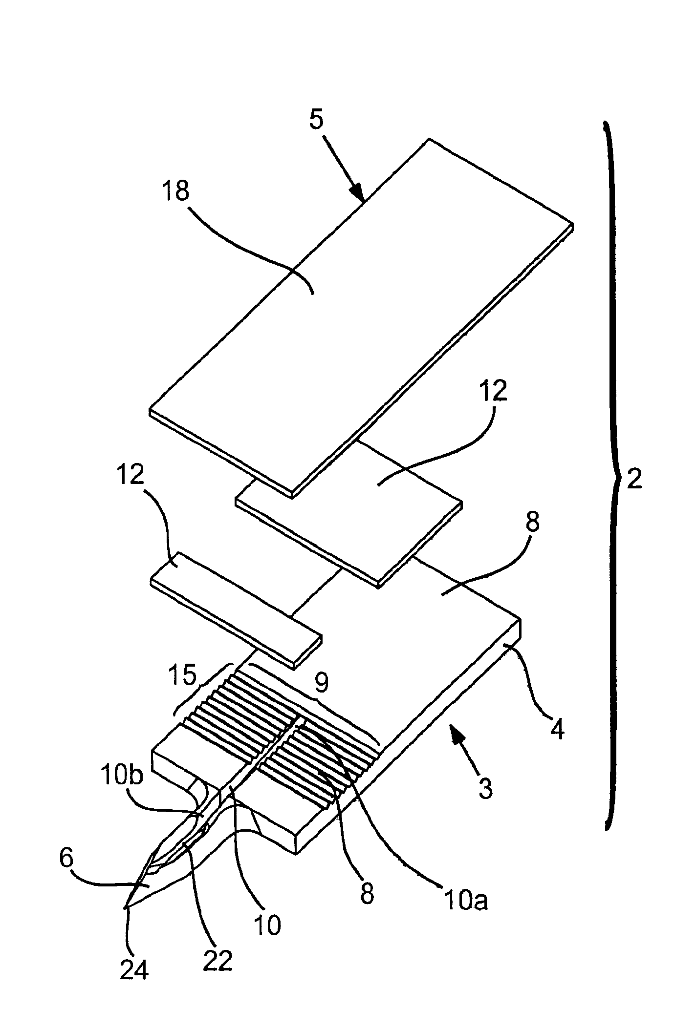
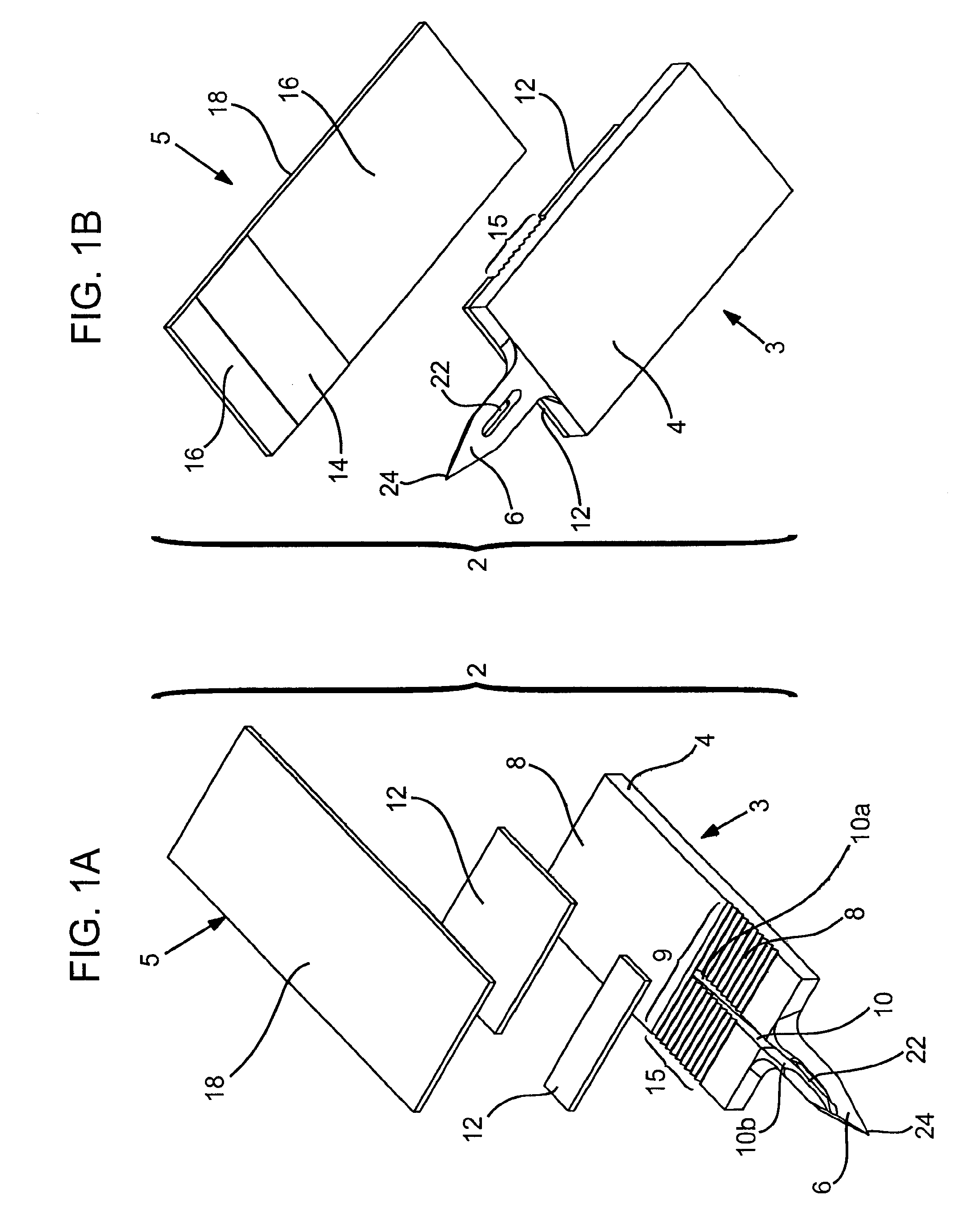
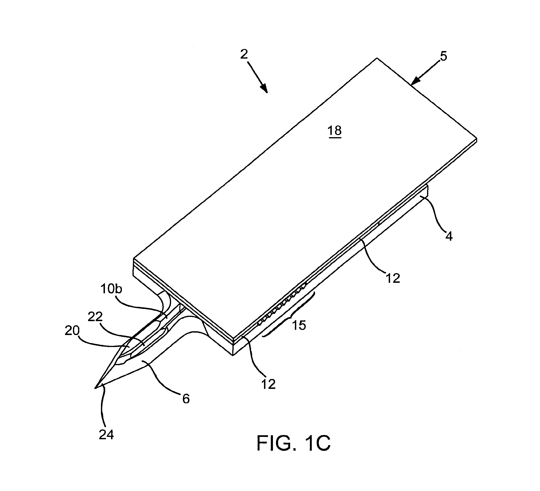
Abstract of Disclosure Devices, systems and methods are provided for piercing the skin, accessing and collecting physiological sample therein, and measuring a characteristic, e.g., an analyte concentration, of the sampled physiological sample. The subject devices are in the form of a test strip which include a biosensor and at least one skin-piercing element which is a planar extension of a portion of the biosensor. At least one fluid pathway resides within a portion of the biosensor and within the skin-piercing element. The skin-piercing element has a space-defining configuration therein which acts as a sample fluid pooling area upon penetration into the skin. Systems are provided which include one or more test strip devices and a meter for making analyte concentration measurements. Methods for using the devices and systems are also provided.

Description

Field of the Invention[0001] The field of this invention is the collection of physiological samples and the determination of analyte concentrations therein.Background of the Invention[0002] Analyte concentration determination in physiological samples is of ever increasing importance to today"s society. Such assays find use in a variety of application settings, including clinical laboratory testing, home testing, etc., where the results of such testing play a prominent role in the diagnosis and management of a variety of disease conditions. Analytes of interest include glucose for diabetes management, cholesterol for monitoring cardiovascular conditions, and the like. In response to this growing importance of analyte concentration determination, a variety of analyte concentration determination protocols and devices for both clinical and home testing have been developed.[0003] In determining the concentration of an analyte in a physiological sample, a physiological sample must first b...

Claims


Application Information

Patent Timeline
IPC IPC(8): A61B5/00A61B5/145A61B5/1473A61B5/15A61B5/157
CPCA61B5/1411A61B5/14514A61B2562/12A61B5/14546A61B2562/0295A61B5/14532A61B5/150022A61B5/150213A61B5/150282A61B5/150358A61B5/150419A61B5/15113A61B5/15117A61B5/1519A61B5/157
Inventor YUZHAKOV , VADIM V.MCALLISTER , DEVIN V.OLSON , LORINLEONG , KOON-WAHTEODORCZYK , MARIAKISER , ERNEST
Owner LIFESCAN INC
Why Eureka
Try Eureka