
Amplifier device for sensors

a technology of amplifier device and sensor, which is applied in the direction of instruments, heat measurement, x/gamma/cosmic radiation measurement, etc., can solve the problems of limited measurement precision, low sensor sensitivity, and strong influence of measurement nois

Inactive Publication Date: 2003-08-07
CENT NAT DE LA RECHERCHE SCI
View PDF12 Cites 2 Cited by
  • Summary
  • Abstract
  • Description
  • Claims
  • Application Information

AI Technical Summary

Benefits of technology

[0011] One object of the invention is also to propose a measuring system whose sensitivity to the physical quantities to be measured is widely increased.

Problems solved by technology

This low sensitivity of sensors induces a limitation of measurement precision and a strong influence of the measurement noise.

Method used


Image

  • Amplifier device for sensors
  • Amplifier device for sensors
  • Amplifier device for sensors

Examples


Embodiment Construction

[0009] The purpose of the invention is to present an amplifying device for the sensors and a measurement system which discards the above mentioned limitations.

[0010] One particular purpose of the invention is to propose an amplifying device allowing to yield a measurement signal at terminals of an additional impedance distinct from the sensor.

[0011] One object of the invention is also to propose a measuring system whose sensitivity to the physical quantities to be measured is widely increased.

[0012] One object of the invention is also to propose a system which features a good measuring precision, which is immune to noise and thus permits a reduction of detection thresholds.

[0013] To fulfil these objectives, the object of the invention is an amplifier for a voltage and / or impedance response sensor. The device includes:

[0014] voltage control means, connected to the sensor output terminals to maintain a noticeably constant voltage between these terminals,

[0015] at least one additional ...


PUM

PropertyMeasurementUnit
constant voltageaaaaaaaaaa
impedanceaaaaaaaaaa
Metal-Oxide-Semiconductoraaaaaaaaaa

Abstract

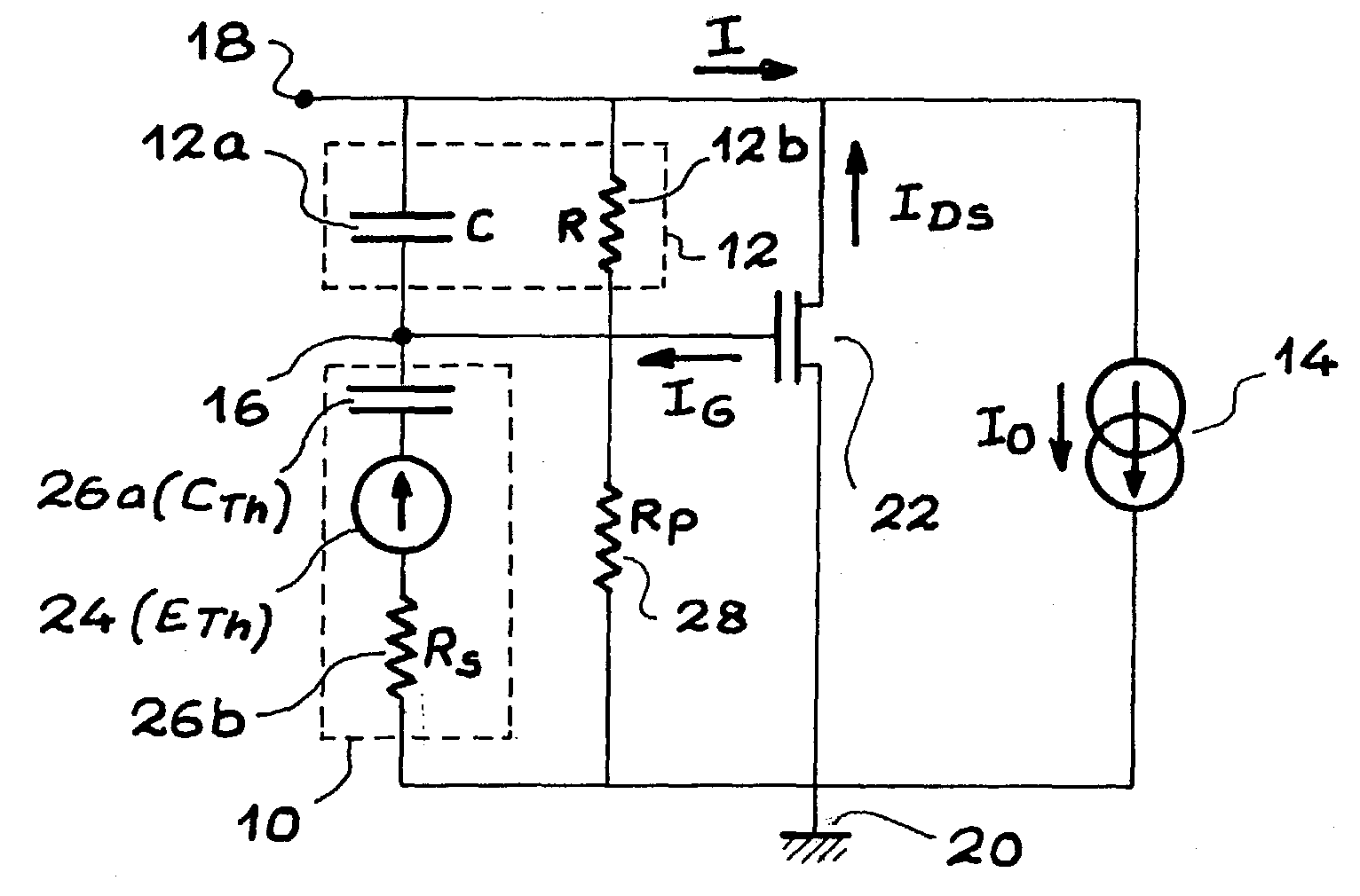
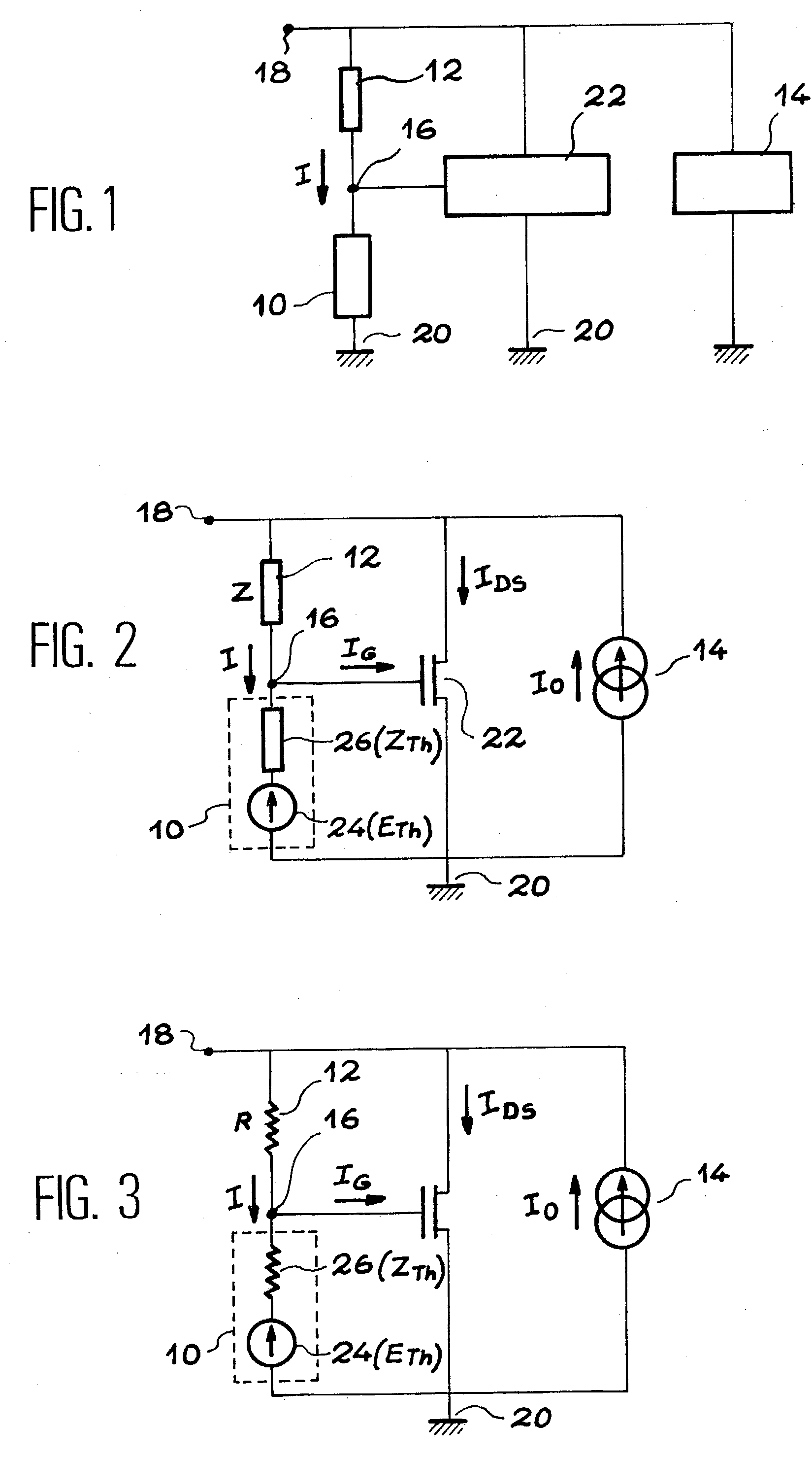
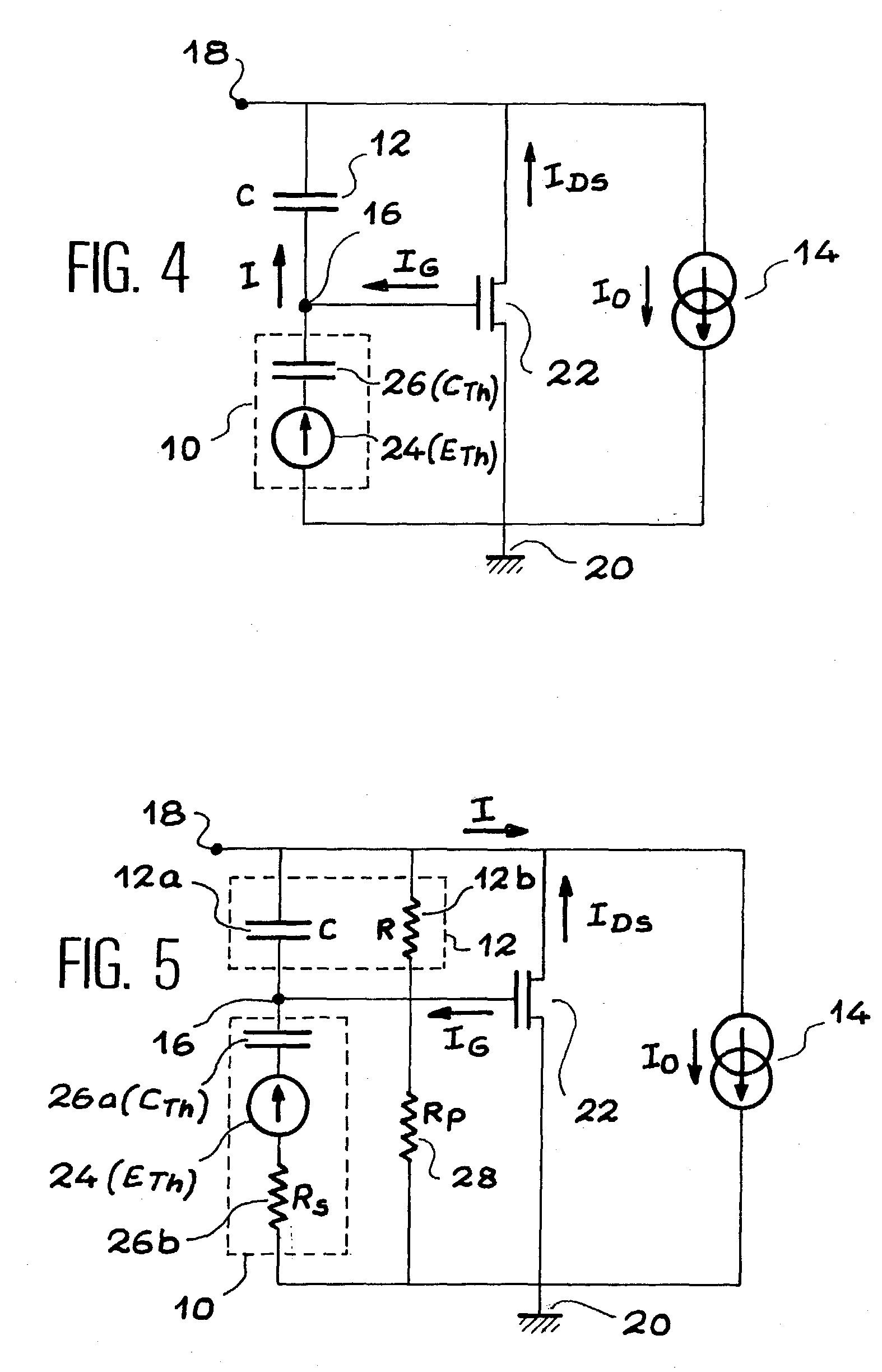
Amplifying device for a sensor (10) delivering a response in voltage or impedance comprising: voltage controlling means (22 connected to output terminals (16, 20) of the sensor to maintain a noticeably constant voltage between the said terminals, at least an additional impedance (12) connected in series with the sensor within a polarisation circuit, between the output terminals (18-16; 18-20) of the said device. Application to temperatures, irradiation levels and pH measurement.

Description

[0001] The present invention relates to an amplifying device for sensors and a measuring system for physical quantities using this device.[0002] The device of the invention is intended, in particular, for voltage and / or impedance response sensors. Such a voltage and / or impedance response sensor is a sensor at which terminals one obtains a voltage variation and / or an impedance variation related to the modification of the physical quantity to which the sensor is sensitive.[0003] The invention has applications in the manufacturing of measuring systems, and mainly measuring systems which comprise miniaturised or embedded (integrated) sensors, known as micro-sensors. As an example, in no way restrictive for the use of the device, the invention may apply to the realisation of thermal probes, dosimeters or photometers.DESCRIPTION OF THE PRIOR ART[0004] The above mentioned voltage and / or impedance response sensors may be modelled by assuming that they are equivalent to a source of a fixed v...

Claims


Application Information

Patent Timeline
Patent Type & Authority Applications(United States)
IPC IPC(8): G01K7/02G01D3/028G01D3/06
CPCG01D3/06
Inventor TEMPLE-BOYER, PIERRESARRABAYROUSE, GERGARDMARTINEZ, AUGUSTINLAUNAY, JEROME
Owner CENT NAT DE LA RECHERCHE SCI
Learn More