Methods for creating woven devices

a technology of woven devices and woven wires, applied in the direction of blood vessels, braids, prostheses, etc., can solve the problems of inability to maintain the shape of the stent, the stent is elongated, and the stent is bent with great car

Inactive Publication Date: 2003-08-07
BOARD OF RGT THE UNIV OF TEXAS SYST
View PDF1 Cites 417 Cited by
  • Summary
  • Abstract
  • Description
  • Claims
  • Application Information

AI Technical Summary

Problems solved by technology

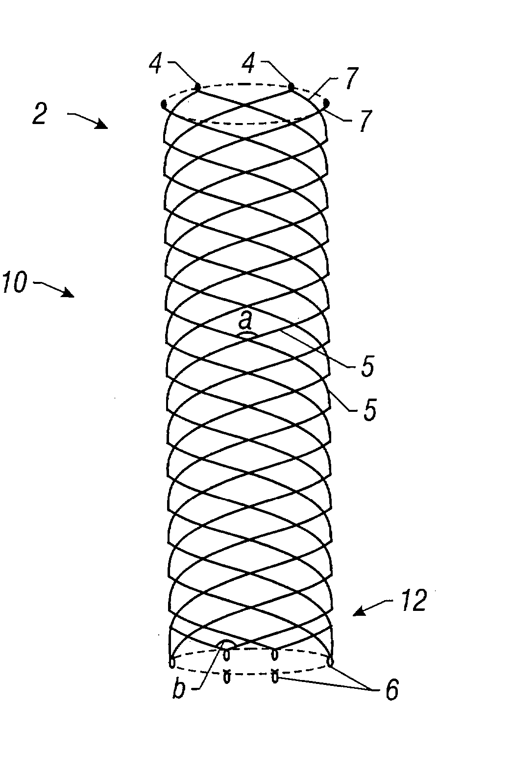
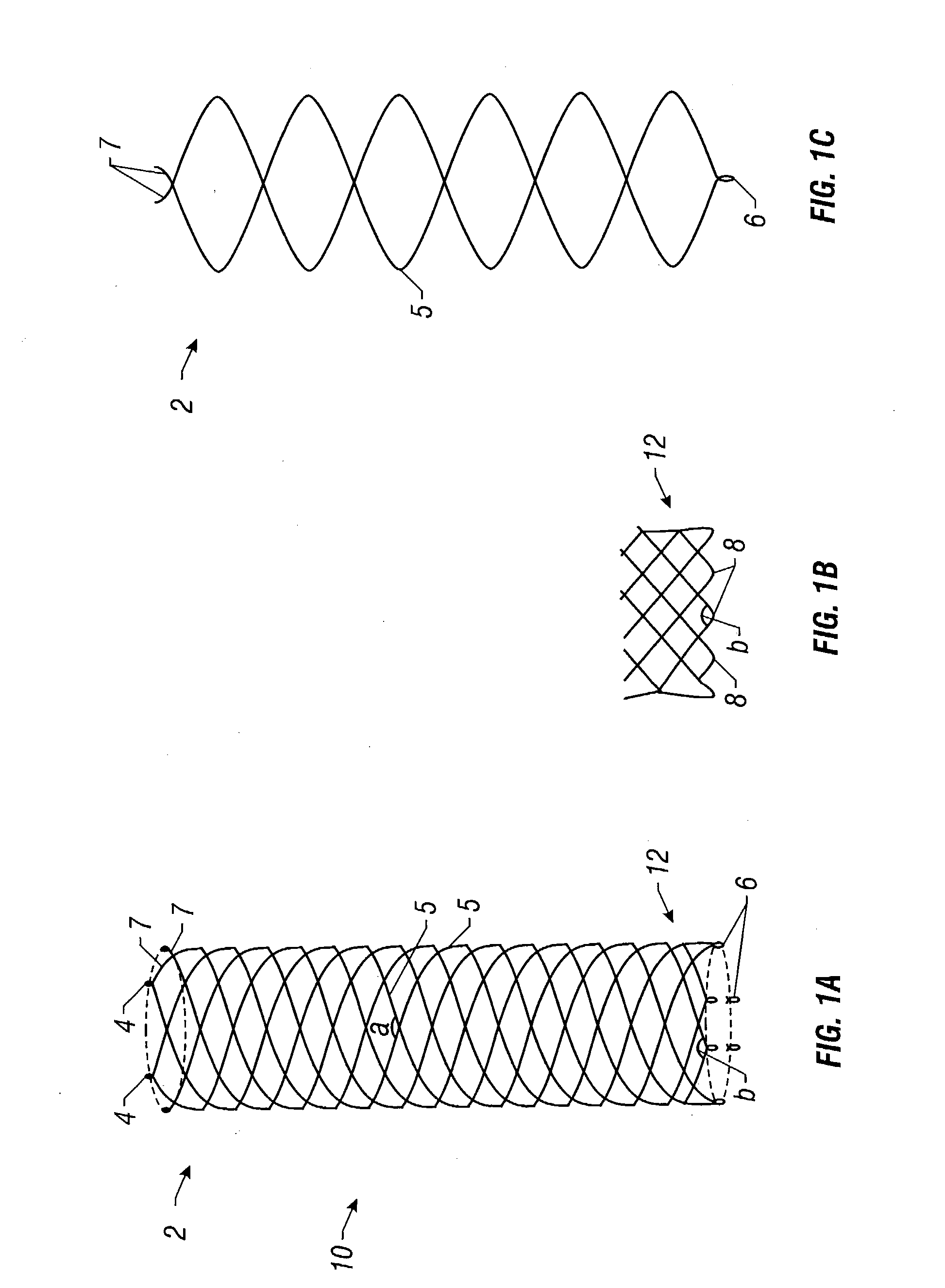
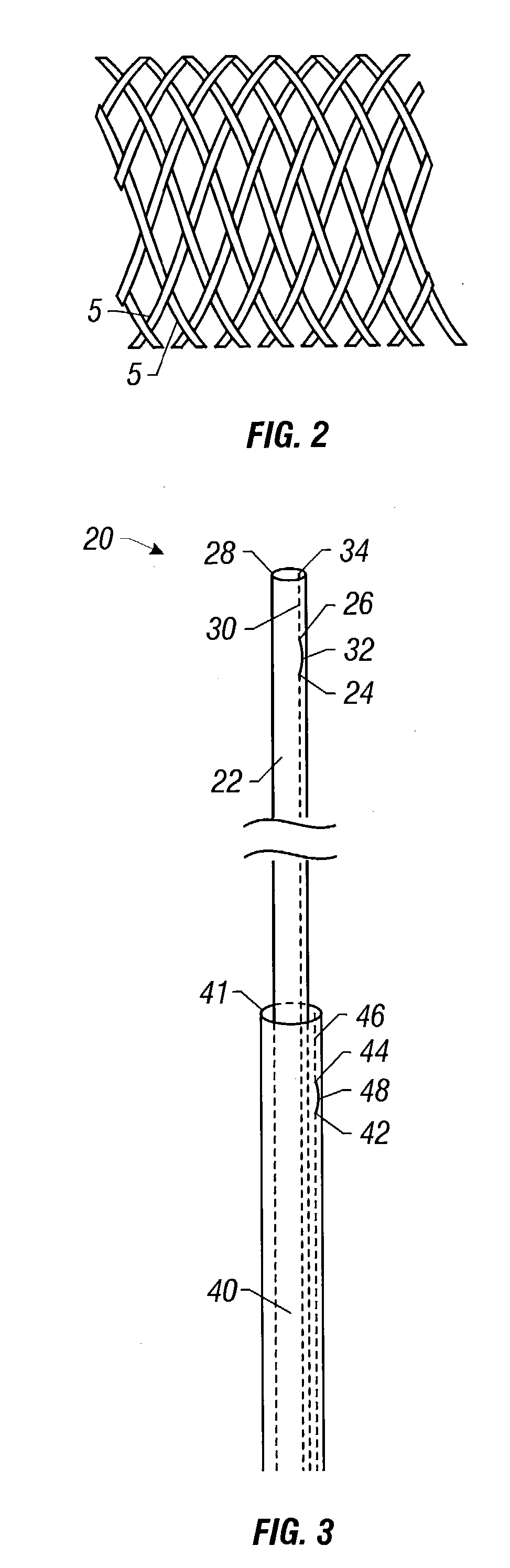
Any discrepancy between the diameters of the stent and the vessel can result in a considerable elongation of the stent.
The disadvantage of a propensity for elongation is that great care must be taken when delivering such a stent in a vessel or non-vascular tubular structure in order to properly position it.
A further disadvantage of intravascular devices formed using a plain weave, is that they are often incapable of maintaining their shape when bent.
Consequently, the diameter of the stent may exceed the diameter of the vessel or structure through which it is traveling, impeding the delivery of the stent or causing the stent to lodge in the vessel.
This problem may be due in part to the use of weave materials such as stainless steel, which exhibit poor shape memory.
This problem may also be due to the free, unclosed wires used to form the stent.
The free sharp ends can create potential complications by penetrating, or perforating the wall of the tubular structure where such a stent is placed.
Further, steps that have been taken to eliminate the free, sharp ends, such as connection with U-shaped members using welding, glue or the like (Wallsten, 1987) are time-consuming and expensive.
The delivery systems for such devices have also suffered from problems relating to the repositionability of the devices as they are delivered into position in the living creature.
In stenting long arterial segments, the contiguously decreasing diameter of the arterial system from the center to the periphery may pose problems.
The aforementioned designs, however, are not capable of catching thrombi effectively at the periphery of the lumen so the patients will practically be unprotected against subsequent peripheral embolization (Xian, 1995; Jaeger, 1998).
Further, most of filters tend to be tilted in the cava which can deter their thrombus-capturing efficacy.
The uniform caliber of cylindrical stents in the prior art used in the ureter, as well as the peristalsis arrested at the proximal end of the stent, has resulted in severe hyperlasia of the urothelium and eventually occlusion of the ureter.
Although coil type occlusion devices have shown at least a degree of utility, they have a number of drawbacks that could be significant in some applications.
Moreover, a long vascular segment is often obliterated because of the frequent need for multiple coils and the coils often remain elongated within the vessel because their unconstrained diameter is larger than the vascular lumen.
However, since optimal arrangement of the coil alone may not prevent migration in some cases, such as high flow conditions or venous placement, a coil anchoring system has been devised (Knya et al., 1998).
Although an anchoring system may stabilize a coil conglomerate within the vasculature, significantly reducing or eliminating the possibility of coil migration, such a system may render the coil non-repositionable.
Although such non-coil devices may be repositionable, they too exhibit drawbacks.
For instance, the quadruple-disc device is several centimeters long in an elongated fashion, making difficult to keep the superselective position of the catheter tip during deployment.
The multiple rigid connections between the layers and the relative long and rigid connection between the occluder and the delivery cable further increase this drawback.
A common disadvantage of both designs is that they lack guidewire compatibility.
Another relative disadvantage of both devices is their cost of manufacturing.
Because of the size of the delivery sheath, such a device is not suitable for the treatment of patients with a body weight of less than 8 kg.
Using even a larger umbrella, this procedure is not recommended for the treatment of the lesions with a diameter of 8 mm or above (Latson, 1991).
One of the main drawbacks of the Rashkind umbrella is that it is not suitable for occlusion of all types of PDA.
Longer PDA may hinder the discs to be positioned in the proper way, that is, parallel to each other, thereby deteriorating its self-anchoring.
Another disadvantage of the umbrella is that the occluding capacity of the design depends exclusively on the thrombogenicity of the porous Dacron material, frequently resulting in partial and lengthy occlusion.
Formerly, detachable and non detachable balloons were used for this purpose, but they did not cause satisfactory ureteral occlusion.
Migration as well as deflation of the balloons occurred relatively frequently (Gunter, 1984; Papanicolau, 1985) leading to recurrence of the urine leakage.
A silicone ureteral occluder was developed and used with only limited success because of device migration (Sanchez, 1988).
This resulted in repositioning and consequent incomplete ureteral occlusion.
The lack of appropriate self-anchoring results in coil migration which eventually deteriorates the occlusive effect.
Problems pointed out in the foregoing are not intended to be exhaustive but rather are among many that tend to impair the effectiveness of previously known stents, occluders and filters.
Other noteworthy problems may also exist; however, those presented above should be sufficient to demonstrate that previous techniques appearing in the art have not been altogether satisfactory, particularly in providing flexible, self-expanding, repositionable stents, occluders and filters.
As a result of only partially covering a body, blood or other bodily fluids may flow through the bare portion of the body relatively unimpeded by the graft material.

Method used


Image

  • Methods for creating woven devices
  • Methods for creating woven devices
  • Methods for creating woven devices

Examples


Embodiment Construction

[0130] 1. Stents

Straight Stents

[0131] With reference to the illustrative embodiment shown in FIG. 1A, there is shown a stent for insertion and delivery into an anatomical structure. The stent includes a plurality of wires 5 which may be arranged in a plain weave so as to define an elastically deformable body 10. As used herein, "elastically deformable" means that the deformation of such a body is non-permanent and an original or initial shape may be substantially recovered, or regained, upon the release of a force (which may be mechanical, electromagnetic, or any other type of force). As used herein, "substantially recovered" means that recovery need not be such that the exact, original shape be regained. Rather, it means that some degree of plastic deformation may occur. In other words, recovery need not be total. Such elastic deformability may be achieved by utilizing the superelastic properties of suitable shape memory wires, which are discussed below.

[0132] U.S. Pat. No. 4,655,7...


PUM

PropertyMeasurementUnit
sizeaaaaaaaaaa
angleaaaaaaaaaa
diameteraaaaaaaaaa

Abstract

Self-expandable, woven intravascular devices for use as stents (both straight and tapered), filters (both temporary and permanent) and occluders for insertion and implantation into a variety of anatomical structures. The devices may be formed from shape memory metals such as nitinol. The devices may also be formed from biodegradable materials. Delivery systems for the devices include two hollow tubes that operate coaxially. A device is secured to the tubes prior to the implantation and delivery of the device by securing one end of the device to the outside of the inner tube and by securing the other end of the device to the outside of the outer tube. The stents may be partially or completely covered by graft materials, but may also be bare. The devices may be formed from a single wire. The devices may be formed by either hand or machine weaving. The devices may be created by bending shape memory wires around tabs projecting from a template, and weaving the ends of the wires to create the body of the device such that the wires cross each other to form a plurality of angles, at least one of the angles being obtuse. The value of the obtuse angle may be increased by axially compressing the body.

Description

[0001] The present application claims priority to U.S. Provisional Patent Application Serial No. 60 / 118,211 file Feb, 1, 1999 and U.S. Provisional Patent Application Serial No. 60 / 125,191 filed Mar. 18, 1999. The entire texts of the above-referenced disclosures are specifically incorporated by reference herein without disclaimer.[0002] 1. Field of the Invention[0003] The present invention relates generally to intravascular devices. More particularly, it concerns self-expandable woven intravascular devices for use as stents, occluders or filters, the methods of making the same, and the apparatus and methods for delivery of the same into a living creature.[0004] 2. Description of Related Art[0005] Intravascular devices that serve as stents or filters constructed using a plain weave, such as the stent disclosed in U.S. Pat. No. 4,655,771 to Wallsten (hereinafter, the WALLSTENT), have a propensity to show a high-degree of elongation axially with diameter reduction. This is especially si...

Claims


Application Information

Patent Timeline
Patent Type & Authority Applications(United States)
IPC IPC(8): A61F2/00A61F2/01A61F2/04A61F2/90
CPCA61F2/04A61F2230/0078A61F2/90A61F2/95A61F2/962A61F2002/011A61F2002/075A61F2002/077A61F2002/9511A61F2210/0014A61F2250/0039A61B2017/00526A61F2/01D04C1/06D04C3/48D10B2509/06A61F2002/016A61F2002/018A61F2230/0006A61F2230/001A61F2230/0067A61F2230/0069A61F2230/0076A61F2230/008A61F2230/0091A61F2230/0093A61F2220/0016A61F2220/005A61F2220/0058A61F2220/0075A61F2230/0015A61F2230/0065A61F2/07A61F2210/0004A61F2/0105A61F2/0108A61F2/011A61F2/88
Inventor HYODOH, HIDEKIKONYA, ANDRASWRIGHT, KENNETH C.
Owner BOARD OF RGT THE UNIV OF TEXAS SYST
Why Eureka
Try Eureka