Environmental scanning electron microscope

an electron microscope and scanning electron technology, applied in the direction of liquid/fluent solid measurement, particle separator tubes, separation processes, etc., can solve the problem of catastrophic scattering effect of electron beams, and achieve the effect of improving detection

Inactive Publication Date: 2003-09-11
DANILATOS GERASIMOS DANIEL
View PDF9 Cites 37 Cited by
  • Summary
  • Abstract
  • Description
  • Claims
  • Application Information

AI Technical Summary

Benefits of technology

0015] It is an object of the present invention to provide an improved device to substantially overcome or ameliorate the above mentioned disadvantages, and a further object to provide improved detection means in the gaseous environment of the specimen chamber.

Problems solved by technology

This is in contrast to the placing of a final aperture, as in the low vacuum SEMs, several mm above the end of the final lens, substantially at the principal plane of the lens, which creates an obstruction between the specimen and the aperture, and which increases the travel distance in the gas from the final PLA to the specimen thus creating a catastrophic scattering effect on the electron beam.

Method used


Image

  • Environmental scanning electron microscope
  • Environmental scanning electron microscope
  • Environmental scanning electron microscope

Examples


Embodiment Construction

[0048] To assist with understanding of the invention, reference will now be made to the accompanying drawings, which embody some examples of the invention.

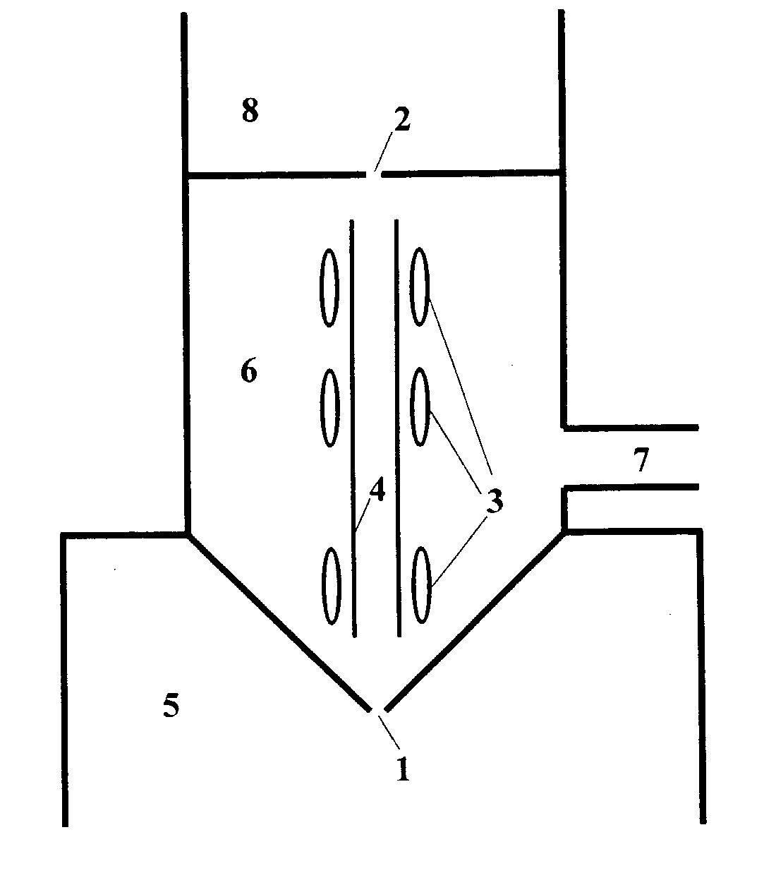
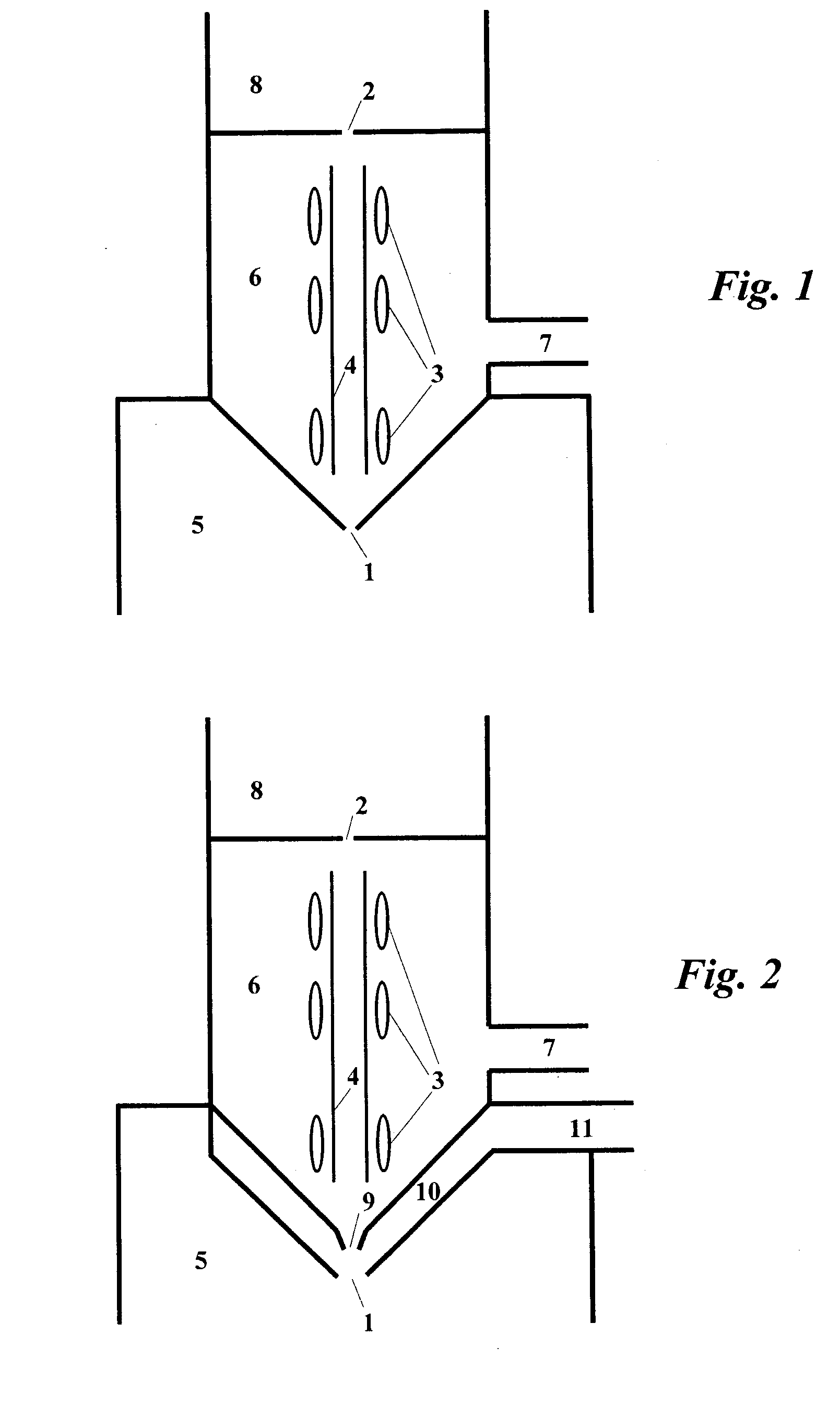
[0049] One embodiment of a device of the present invention is shown in FIG. 1. An electron or ion beam is generated, focussed and scanned by an electron optics column by known means, the relevant parts only of which are drawn in said FIG. 1. Apertures 1 and 2 are shown with scan coils 3 being positioned between. The aperture 2 is the entry port for the beam from the upper electron optics column (not shown) containing an electron / ion gun and other electromagnetic lenses, apertures and pumping means according to known art. The beam travels through column liner pipe 4 and exits via the aperture 1 into a specimen chamber 5. An intermediate chamber 6 is located in the space between the apertures 1 and 2 is evacuated via port 7 with a pump (not shown). The column liner 4 freely communicates with the space in the intermediate chamber 6 a...


PUM

PropertyMeasurementUnit
diameteraaaaaaaaaa
pressureaaaaaaaaaa
distanceaaaaaaaaaa

Abstract

The invention provides for a scanning electron or ion beam instrument capable of transferring the beam from a high vacuum chamber (8) into a high pressure chamber (5) via aperture (1) and aperture (2). The beam is deflected and scanned by coils (3) generally positioned between apertures (1) and (2). The amplitude of deflection of the beam over a specimen placed inside chamber (5) is substantially larger than the diameter of aperture (1). Leaking gas through aperture (1) is removed via port (7) by appropriate pumping apparatus. The size of aperture (1) is such that the pressure in chamber (6) combined with the supersonic jet and shock waves naturally forming therein do not result in catastrophic electron beam loss in chamber (6). The addition of appropriate detection means result in an instrument characterised by superior performance over prior art by way of better field of view at low magnification, better vacuum system and improved detection and imaging capabilities.

Description

[0001] The present invention relates to the technical field of electron and ion microscopy as well as to electron and ion beam technologies in general.[0002] Electron microscopes in general and scanning electron microscopes (SEM) in particular use an electron beam probe to examine specimens. The electron beam requires a good vacuum where it is generated by an electron gun and propagated through focussing lenses all the way to the specimen. In addition, many of the detection means used to detect the emerging signals from the beam-specimen interaction also require a vacuum condition in which the specimen is severely limited. In the past, this meant that only dehydrated specimens could be used. In addition, because the electron beam delivers an electric current, the specimen should generally have a conductive surface to prevent accumulation of charge that hinders normal operation of the instrument. This meant that generally an insulating surface could not be examined. However, the more...

Claims


Application Information

Patent Timeline
Patent Type & Authority Applications(United States)
IPC IPC(8): G01Q30/04G01Q30/08H01J37/301
CPCH01J37/301H01J2237/188H01J2237/2608H01J2237/2605H01J2237/2002
Inventor DANILATOS, GERASIMOS DANIEL
Owner DANILATOS GERASIMOS DANIEL
Why Eureka
Try Eureka