
Apparatus and methods for analyte measurement and immuno assay

analyte measurement and immuno assay technology, applied in the field of apparatus and methods for analyte measurement and immuno assay, can solve the problems of variability of fluid test parameters from cartridge to cartridge, increased analysis cost of laboratory testing, and adverse to patient condition or prognosis

Active Publication Date: 2003-09-11
ABBOTT POINT CARE
View PDF32 Cites 516 Cited by
  • Summary
  • Abstract
  • Description
  • Claims
  • Application Information

AI Technical Summary

Benefits of technology

[0012] It is therefore an objective of the present invention to provide improved apparatus and methods for the determination of analytes in a liquid sample, which avoid the aforementioned disadvantages and drawbacks.

Problems solved by technology

Laboratory testing increases the cost of analysis and delays the results.
In many circumstances, delay can be detrimental to a patient's condition or prognosis, such as for example the analysis of markers indicating of myocardial infarction.
A potential problem with disposable devices is variability of fluid test parameters from cartridge to cartridge due to manufacturing tolerances or machine wear.
Because a quantitative immunoassay typically requires multiple steps (eg. a binding step followed by a rinse step with a solution that may or may not contain a second reagent), most of the foregoing methods are either operated manually, or require bulky machinery with complex fluidics.

Method used


Image

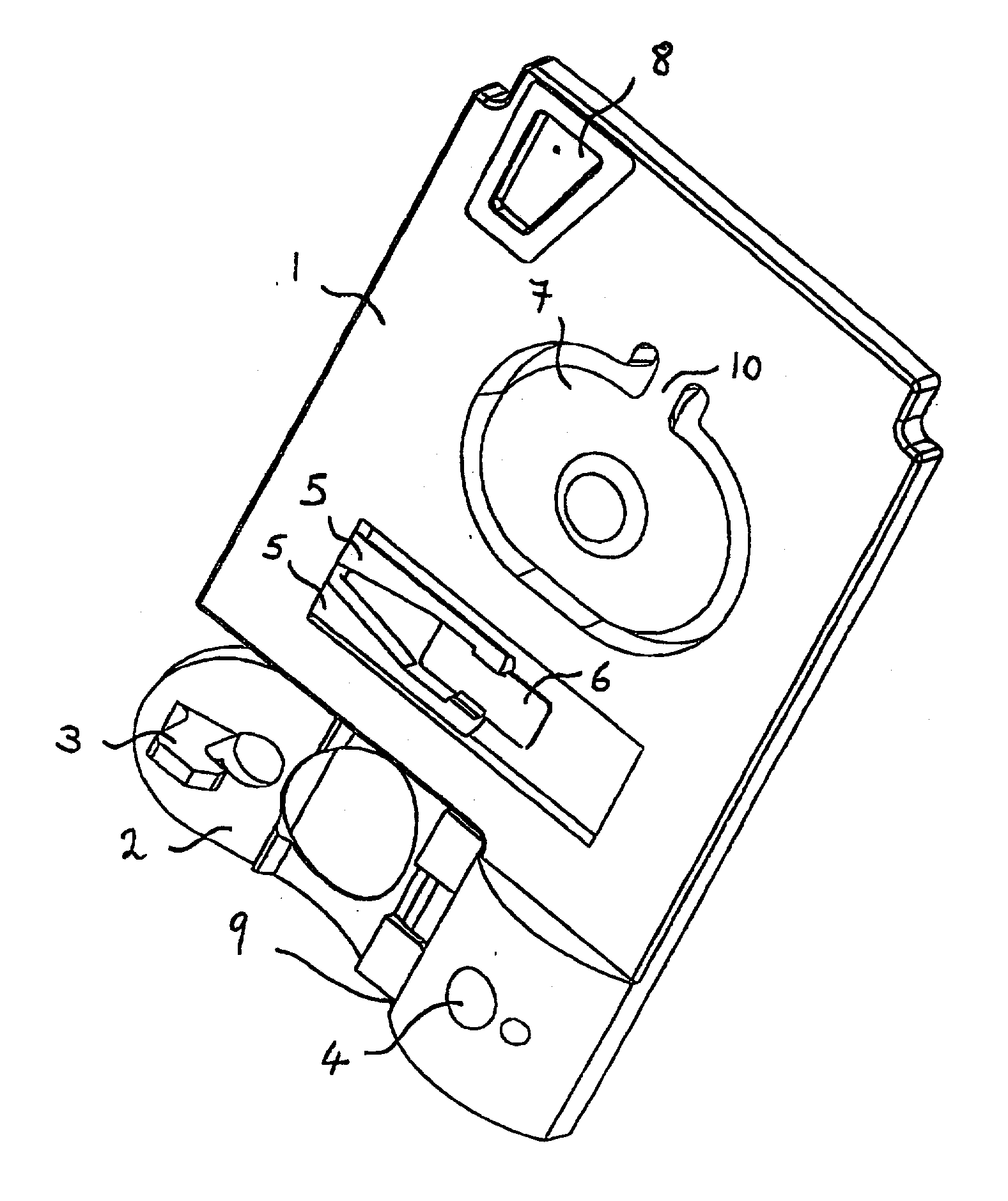
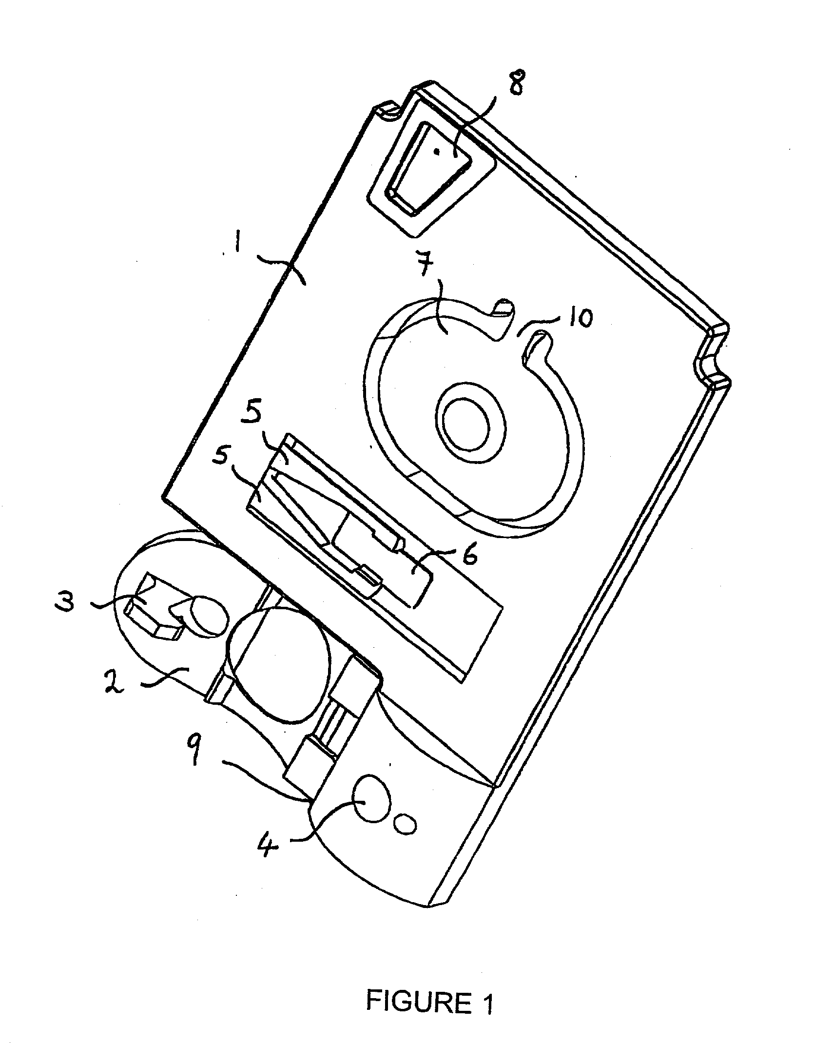
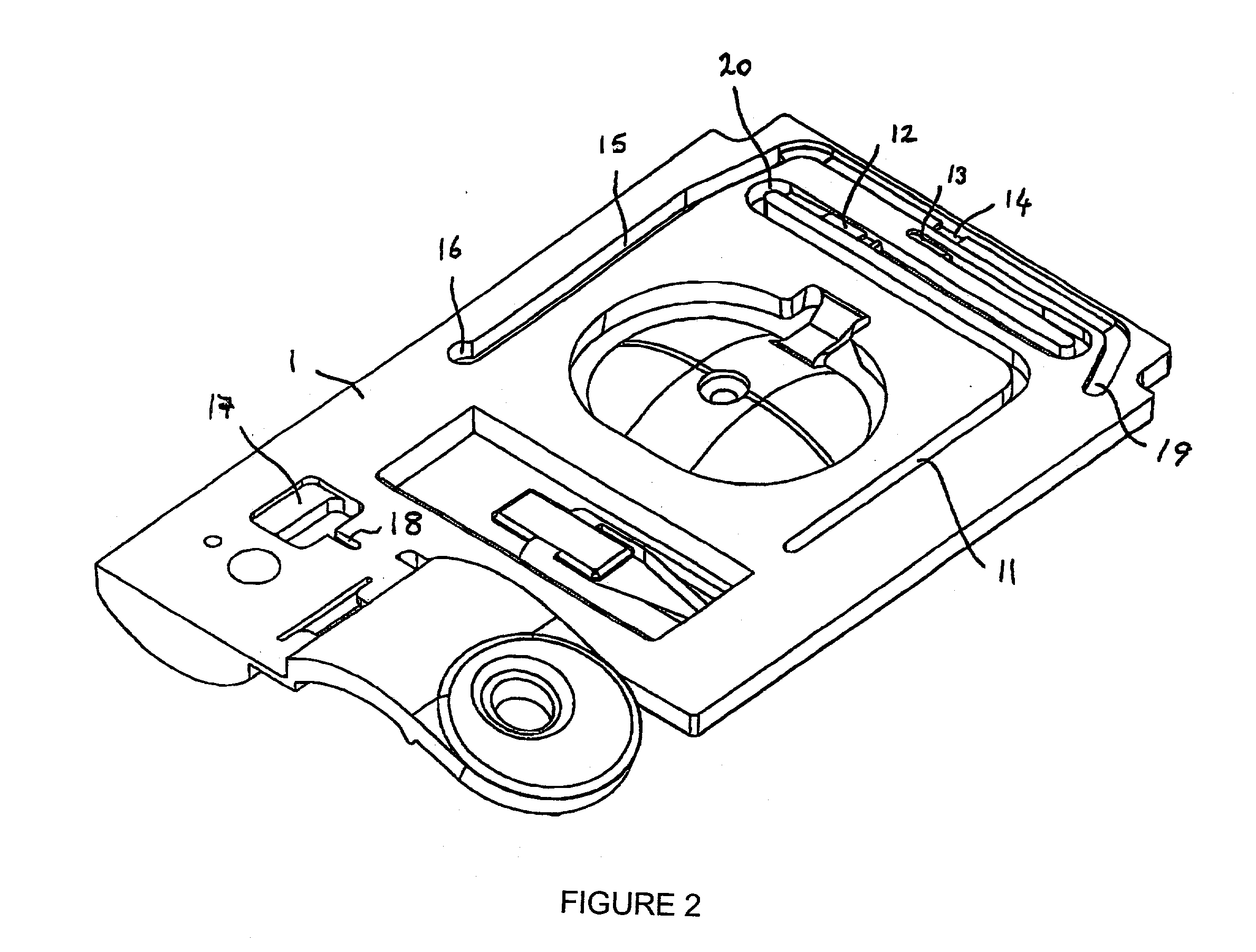
  • Apparatus and methods for analyte measurement and immuno assay
  • Apparatus and methods for analyte measurement and immuno assay
  • Apparatus and methods for analyte measurement and immuno assay

Examples


example 1

[0067] Referring now to FIG. 7, which illustrates the principle of an amperometric immunoassay according to specific embodiments of the present invention for determination of troponin I (TnI), a marker of cardiac function. A blood sample, for example, is introduced into the sample holding chamber of a cartridge of the present invention, and is amended by a conjugate molecule comprising alkaline phosphatase enzyme (AP) covalently attached to a polyclonal anti-troponin I antibody (aTnI) 71. This conjugate specifically binds to the TnI, 70, in the blood sample, producing a complex made up of TnI bound to the AP-aTnI conjugate. In a capture step, this complex binds to the capture aTnI antibody 72 attached on, or close to, the immunosensor. The sensor chip has a conductivity sensor which is used to monitor when the sample reaches the sensor chip. The time of arrival of the fluid can be used to detect leaks within the cartridge: a delay in arrival signals a leak. The position of the sampl...

example 2

Method of Use a Cartridge of claim 1

[0086] In a first cartridge embodiment, one exemplary analyte assay protocol using a cartridge of claim 1 is described. An unmetered fluid sample is introduced into sample chamber 34 of a cartridge according to claim 1, through sample entry port 4. Capillary stop 25 prevents passage of the sample into conduit 11 at this stage, and conduit 34 is filled with the sample. Lid 2 is closed to prevent leakage of the sample from the cartridge. The cartridge is then inserted into a reading apparatus, such as that disclosed in U.S. Pat. No. 5,821,399 to Zelin, which is hereby incorporated by reference. Insertion of the cartridge into a reading apparatus activates the mechanism which punctures a fluid-containing package located at 42 when the package is pressed against spike 38. Fluid is thereby expelled into the second conduit, arriving in sequence at 39, 20, 12 and 11. The constriction at 12 prevents further movement of fluid because residual hydrostatic p...

example 3

Method of Use of the Cartridge of claim 2

[0095] The cartridge of claim 2 comprises all the elements of the cartridge of claim 1 together with a closeable valve, preferably located between the sensor chamber and the waste chamber. The method of use of the cartridge of claim 2 is herein illustrated by a specific embodiment in which the concentration of HCG is determined within a blood sample, which is introduced into the sample chamber of said cartridge. In the following time sequence, time zero (t=0) represents the time at which the cartridge is inserted into the cartridge reading device. Times are given in minutes. Between t=0 and t=1.5, the cartridge reading device makes electrical contact with the sensors through pads 91, 93, 95, and 97, and performs certain diagnostic tests. Insertion of the cartridge perforates the foil pouch introducing fluid into the second conduit as previously described. The diagnostic tests determine whether fluid or sample is present in the conduits using ...


PUM

PropertyMeasurementUnit
Capillary waveaaaaaaaaaa
Pressureaaaaaaaaaa
Flow rateaaaaaaaaaa

Abstract

The present invention relates to an apparatus for conducting a variety of assays for the determination of analytes in liquid samples, and relates to the methods for such assays. In particular, the invention relates to a single-use cartridge designed to be adaptable to a variety of real-time assay protocols, preferably assays for the determination of analytes in biological samples using immunosensors or other ligand / ligand receptor-based biosensor embodiments. The cartridge provides novel features for processing a metered portion of a sample, for precise and flexible control of the movement of a sample or second fluid within the cartridge, for the amending of solutions with additional compounds during an assay, and for the construction of immunosensors capable of adaptation to diverse analyte measurements. The disclosed device and methods of use enjoy substantial benefits over the prior art, including simplicity of use by an operator, rapid in situ determinations of one or more analytes, and single-use methodology that minimizes the risk of contamination of both operator and patient. The disclosed invention is adaptable to the point-of-care clinical diagnostic field, including use in accident sites, emergency rooms, surgery, nursing homes, intensive care units, and non-medical environments.

Description

I. FIELD OF THE INVENTION[0001] In its broadest aspect, the invention relates to an apparatus and method for rapid in situ determinations of analytes in liquid samples that is capable of being used, for example, in the point-of-care clinical diagnostic field, including use at accident sites, emergency rooms, in surgery, in intensive care units, and also in non-medical environments.[0002] The present invention thus relates to an apparatus and its method of use for determining the presence and / or concentrations of analytes in a liquid sample. More particularly, the invention provides single-use disposable cartridges, adapted for conducting diverse real-time or near real-time assays of analytes. The invention further relates to a cartridge that provides novel features for processing a metered portion of a sample. The cartridge incorporates novel features for precise and flexible control of the movement of a sample or a second fluid within the cartridge, and for the optional amending of...

Claims


Application Information

Patent Timeline
IPC IPC(8): B01L3/00C12M1/34G01N27/28G01N27/327G01N27/416G01N33/543G01N35/04G01N35/08
CPCB01L3/502723G01N33/543B01L3/502738B01L2200/10B01L2300/0663B01L2300/0816B01L2300/087B01L2400/0421B01L2400/046B01L2400/0481B01L2400/0683G01N33/54366G01N35/08G01N2035/0436B01L3/50273
Inventor DAVIS, GRAHAMLAUKS, IMANTS R.LIN, CHAOMILLER, CARY JAMES
Owner ABBOTT POINT CARE
Learn More