Electrovalve for controlling an injection valve in an internal combustion engine

a technology for injectors and valves, which is applied in the direction of valve operating means/release devices, machines/engines, and fluid pressure injection control. it can solve the problems of armature bounce, disadvantageous oscillation and/or bounce, and impaired control of injection procedures

Inactive Publication Date: 2003-09-25
ROBERT BOSCH GMBH
View PDF0 Cites 14 Cited by
  • Summary
  • Abstract
  • Description
  • Claims
  • Application Information

AI Technical Summary

Problems solved by technology

A known disadvantage of solenoid valves is the armature bounce.
The impact of the control valve element on the valve seat may result in a disadvantageous oscillation and/or bounce of the control valve element on the valve seat, due to which the control of the injection procedure is impaired.
The effectively braked mass, and therefore the kinetic energy of the armature striking the valve seat, which causes bounce, are reduced through the two-part embodiment of the armat

Method used


Image

  • Electrovalve for controlling an injection valve in an internal combustion engine
  • Electrovalve for controlling an injection valve in an internal combustion engine
  • Electrovalve for controlling an injection valve in an internal combustion engine

Examples


Embodiment Construction

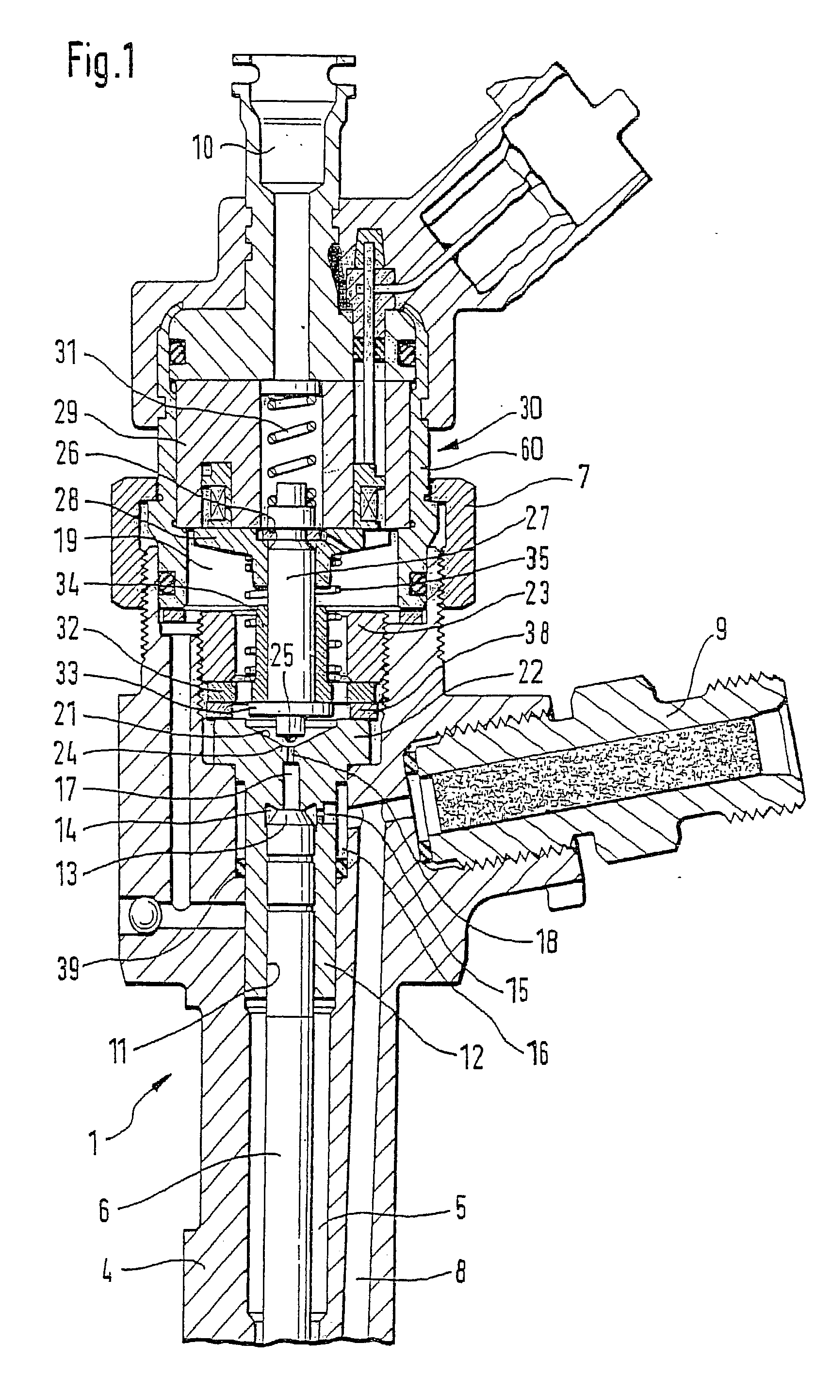
[0017] FIG. 1 shows the upper part of a fuel injector 1 known from the related art, which is intended for use in a fuel injection system equipped with a high-pressure fuel storage cylinder which is continuously supplied with high-pressure fuel by a high-pressure delivery pump. Fuel injector 1, illustrated, has a valve housing 4 having a longitudinal bore 5, in which a valve plunger 6 is arranged, one end of which acts on a valve needle arranged in a nozzle body (not shown). The valve needle is arranged in a pressure chamber which is supplied with fuel standing under high pressure via a pressure bore 8. During an opening stroke movement of valve plunger 6, the valve needle is lifted against the closing force of a spring by the high pressure of the fuel in the pressure chamber, which is continuously applied to a pressure shoulder of the valve needle. The fuel is injected into the combustion chamber of the internal combustion engine through an injection opening which is then connected ...


PUM


Abstract

In a solenoid valve for controlling a fuel injector of an internal combustion engine, which has an electromagnet (29), a movable armature having an armature plate (28) and an armature pin (27), and a control valve element (25), which is moved with the armature and works together with a valve seat (24), for opening and closing a fuel drain channel (17) of a control pressure chamber (14) of the fuel injector (1), this armature plate (28) being mounted on the armature pin (27) so it is movable by sliding under the effect of its inertial mass in the closing direction of the control valve element (25) against the tension of a return spring (35) acting on the armature plate (28), in order to be able to easily set the maximum slide path of the armature plate (28), an actuator is provided on the armature plate which is arranged on a section (42) of the armature plate (28) facing away from the electromagnet (29) and is adjustable in the sliding direction of the armature plate (28) relative to a face (41) of the armature plate facing the electromagnet.

Description

BACKGROUND INFORMATION[0001] The present invention relates to a solenoid valve for controlling a fuel injector of an internal combustion engine according to the definition of the species in claim 1.[0002] Such a solenoid valve, known from German Patent Application 197 08 104 A1, for example, is used to control the fuel pressure in the control pressure chamber of a fuel injector, for example in the injector of a common rail injection system. The movement of a valve plunger, using which an injection opening of the fuel injector is opened or closed, is controlled via the fuel pressure in the control pressure chamber. The known solenoid valve has an electromagnet arranged in a housing part, a movable armature, and a control valve element which is moved using the armature, is acted upon by a closing spring in the closing direction, works together with a valve seat of the solenoid valve and thus controls the fuel discharge out of the control pressure chamber. A known disadvantage of solen...

Claims


Application Information

Patent Timeline
IPC IPC(8): F02M47/00F02M47/02F02M51/00F02M51/06F02M59/46F02M61/16F02M61/20
CPCF02M47/027F02M63/0019F02M2547/003F02M2200/8092F02M2200/306F02M63/0022
Inventor GRYTZ, UWE
Owner ROBERT BOSCH GMBH
Why Eureka
Try Eureka