Performance recovery process for PEM fuel cells

a technology of performance recovery and fuel cells, applied in the direction of fuel cells, solid electrolyte fuel cells, electrical equipment, etc., can solve the problem of substantially the same reduction of fuel cell stack performance, and achieve the effect of restoring performan

Inactive Publication Date: 2003-09-25
AUDI AG
View PDF3 Cites 22 Cited by
  • Summary
  • Abstract
  • Description
  • Claims
  • Application Information

AI Technical Summary

Benefits of technology

0005] Objects of the invention include restoration of performance to fuel cell stacks following loss of performance such as from repetitive freeze / thaw cycles or repetitive boot strap start-up cycles; a fuel cell stack regeneration process which can be monitored for effectiveness;

Problems solved by technology

However, repetitive use of this procedure has been found to reduce fuel cell stack performance in substantially the same fashion as repetitive freeze / thaw cycles.

Method used


Image

  • Performance recovery process for PEM fuel cells
  • Performance recovery process for PEM fuel cells
  • Performance recovery process for PEM fuel cells

Examples


Embodiment Construction

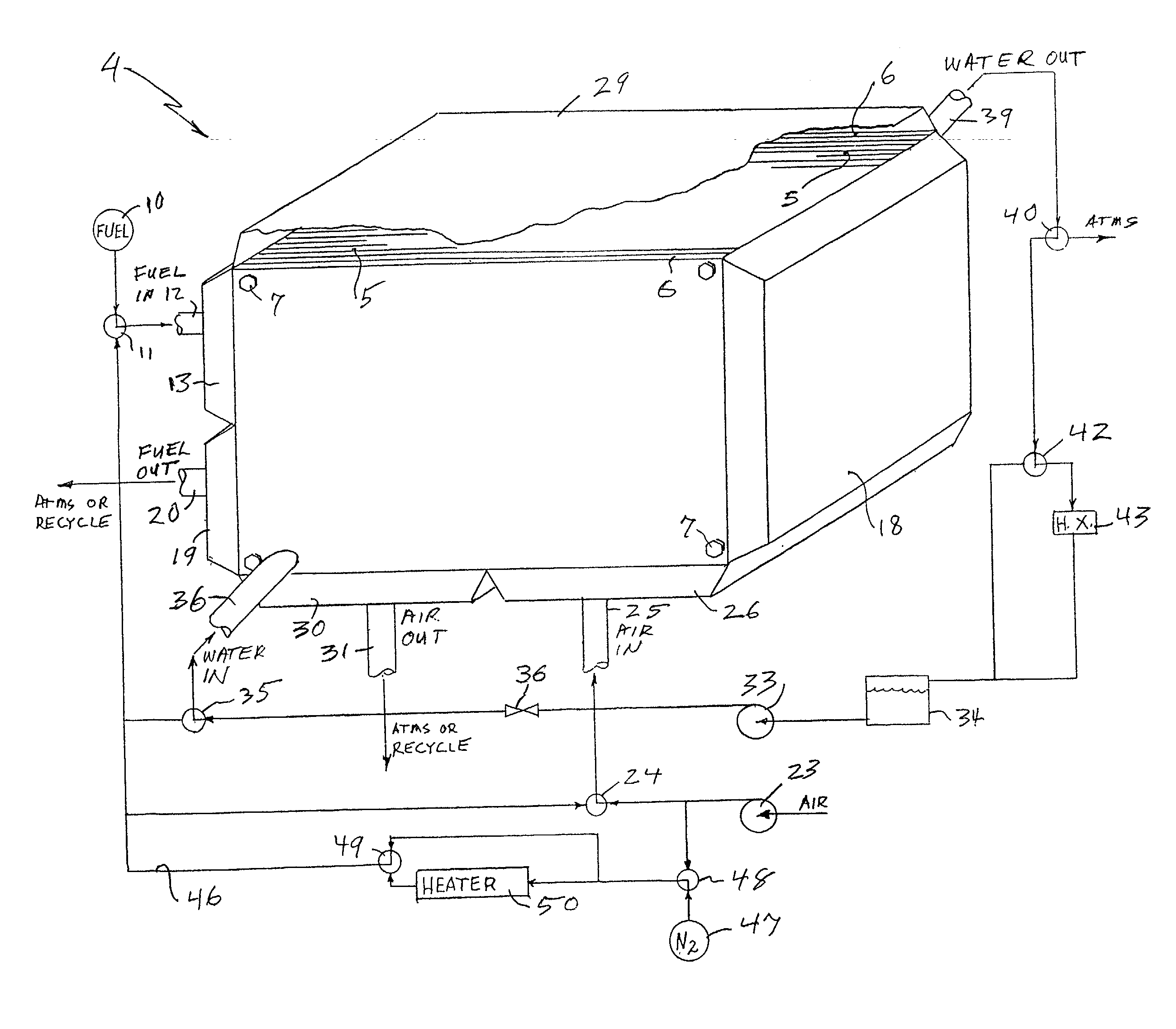
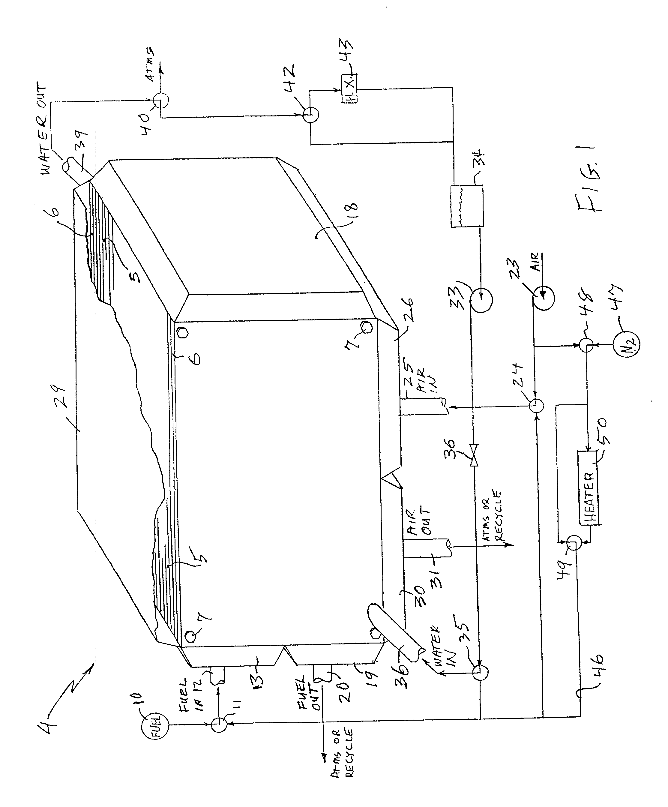
[0016] Referring to FIG. 1, a fuel cell stack 4 comprises a plurality of fuel cells 5 clamped together between pressure plates 6 by bolts 7. Fuel is supplied to the stack 4 from a source 10 through a valve 11, shown in its normal operating position, a fuel inlet 12 and a fuel inlet manifold 13. The fuel flows through the upper halves of the cells 5, to the right as seen in FIG. 1, and is turned around in a manifold 18, after which it flows through the lower half of the cells, to the left as seen in FIG. 1, to a fuel outlet manifold 19 from whence it flows through a fuel outlet 20 either to atmosphere or to some form of known fuel recycle loop (not shown).

[0017] In the example of FIG. 1, the oxidant is air, drawn from the atmosphere by a pump 23, which then flows through a valve 24, shown in its normal operating position, through an air inlet 25 to an air inlet manifold 26. The fuel flows upwardly (as seen in FIG. 1) in the right half of the fuel cells 5, is turned around within a ma...


PUM

PropertyMeasurementUnit
temperaturesaaaaaaaaaa
diameteraaaaaaaaaa
diameteraaaaaaaaaa

Abstract

Recovery of PEM fuel cell performance is achieved by evacuating (61, 62) or by flowing water absorbing gas (46) through, or both, the fuel flow field (12, 13, 19, 20), the air flow field (25, 26, 30, 31), and the water flow field (36, 39), while resistance of the individual cells, or of the fuel cell stack, is measured; the dry out process is continued until the resistance of the cells (or the resistance per cell, measured across the fuel cell stack as a whole), has increased by at least 5 to 1 (preferably 10 to 1) over the normal resistance of the cells. The water absorbing gas may be air (23) or nitrogen (47); it may be at ambient temperature or heated (50).

Description

[0001] This invention relates to restoring performance of PEM fuel cells after performance loss due, for instance, to freeze / thaw cycles and / or "boot strap" startup of frozen fuel cells.[0002] In U.S. Pat. No. 4,294,892, the regeneration or recovery of a fuel cell (restoring the fuel cell to full performance following a loss of performance) is accomplished by reducing the concentration of oxygen on the cathode while maintaining the overall pressure of gas in the cathode oxidant reactant flow fields, either by replacing oxygen with a flow of argon or by shutting off the air discharge. The terminal voltage is preferably reduced to 10% of its original value. Other known methods of regenerating a fuel cell include reducing or stopping the flow of air and substituting a flow of inert gas for the oxidant flow. In most cases, fuel flow continues so as to react with and thereby remove oxygen from the system. In some cases, the load remains connected and in other cases an auxiliary load is s...

Claims


Application Information

Patent Timeline
Patent Type & Authority Applications(United States)
IPC IPC(8): H01M8/04H01M8/10
CPCH01M8/04119Y02E60/50H01M8/04223H01M8/241H01M8/0267H01M8/2484H01M8/0258
Inventor HAGANS, PATRICK L.RESNICK, GENNADY
Owner AUDI AG
Why Eureka
Try Eureka