Ultrasonic receiving apparatus and ultrasonic imaging apparatus

a technology of ultrasonic imaging and receiving apparatus, which is applied in the field of ultrasonic receiving apparatus and ultrasonic imaging apparatus, can solve the problems of blurred synthesized image, inconvenient technique, and difficulty in further miniaturization and integration of elements exceeding the state of the art, and achieve the effect of reducing the multiple reflection of ultrasonic waves and increasing the quality of ultrasonic images

Inactive Publication Date: 2003-09-25
FUJIFILM HLDG CORP +1
View PDF2 Cites 71 Cited by
  • Summary
  • Abstract
  • Description
  • Claims
  • Application Information

AI Technical Summary

Benefits of technology

[0015] The present invention has been achieved in view of the above-described problems. An object of the present invention is, in a photo-detection type ultrasonic receiving apparatus, to increase the quality of the ultrasonic image by reducing the multiple reflection of the ultrasonic wave. A further object of the present invention is to provide an ultrasonic imaging apparatus to be used for medical diagnosis or nondestructive inspection by receiving ultrasonic waves using such an ultrasonic receiving apparatus.
[0020] According to the first aspect of the present invention, since the ultrasonic wave is attenuated by propagating the received ultrasonic wave to the backing portion, it is possible to avoid the influence due to the multiple reflection of the ultrasonic wave. Also, since the light used for detection is guided by the backing portion having an optical transmissibility, it is possible to reduce the attenuation of the optical signal output from the ultrasonic detecting element and to guide the optical signal to the photoelectric conversion unit without decreasing the SN-ratio.
[0021] According to the second aspect of the present invention, it is possible to avoid the influence due to the multiple reflection of the ultrasonic wave by propagating the received ultrasonic wave to the optical transmission path for guiding the light to the ultrasonic detecting element. Also, since the ultrasonic detecting element and the optical transmission path are connected via collimating portion, it is possible to guide the parallel light to the ultrasonic detecting element and to propagate the ultrasonic wave to the optical transmission path such as an optical fiber.

Problems solved by technology

However, according to this technique, since a time lag is generated in the shifting direction of the one-dimensional sensor array, cross-sectional images at different time points are synthesized resulting in a blurred synthesized image.
Accordingly, the technique is not suitable to such a case where images of a living organism as an object are taken in ultrasonic echo observation or the like.
However, although minute processing on elements and wiring to a number of minute elements are required in the case where the two-dimensional sensor array is manufactured using the above-described PZT or PVDF, further miniaturization and integration of elements exceeding the state of the art are difficult.
Also, even when the above-described problems are solved, such problems still remain that the cross talk between elements is increased, the SN-ratio is lowered due to increase of electrical impedance caused from minute wirings, electrodes of minute elements get damaged easily, and so on.
Therefore, it is difficult to achieve the two-dimensional sensor array using the PZT or the PVDF.
However, the photo-detection type ultrasonic sensor has the following problem, that is, multiple reflection of an ultrasonic wave is generated on a backside of the ultrasonic wave receiving surface.
The above described multiple reflection of the ultrasonic wave becomes a cause to decrease the SN-ratio in the ultrasonic image, resulting in a decreased image quality.
However, in the photo-detection type ultrasonic receiving apparatus, since it is necessary to take the optical transmissibility into consideration, the backing material same as that of conventional manner can not be used.

Method used


Image

  • Ultrasonic receiving apparatus and ultrasonic imaging apparatus
  • Ultrasonic receiving apparatus and ultrasonic imaging apparatus
  • Ultrasonic receiving apparatus and ultrasonic imaging apparatus

Examples


first embodiment

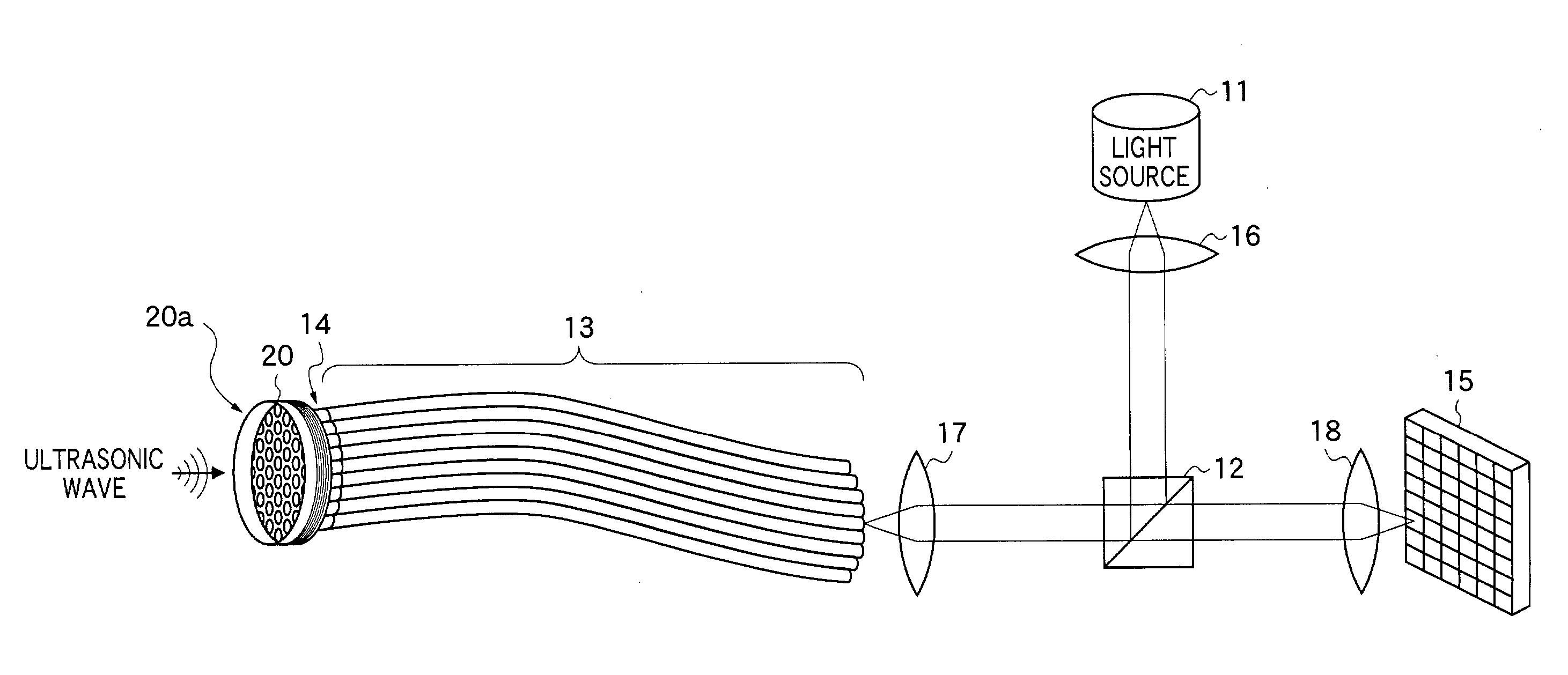
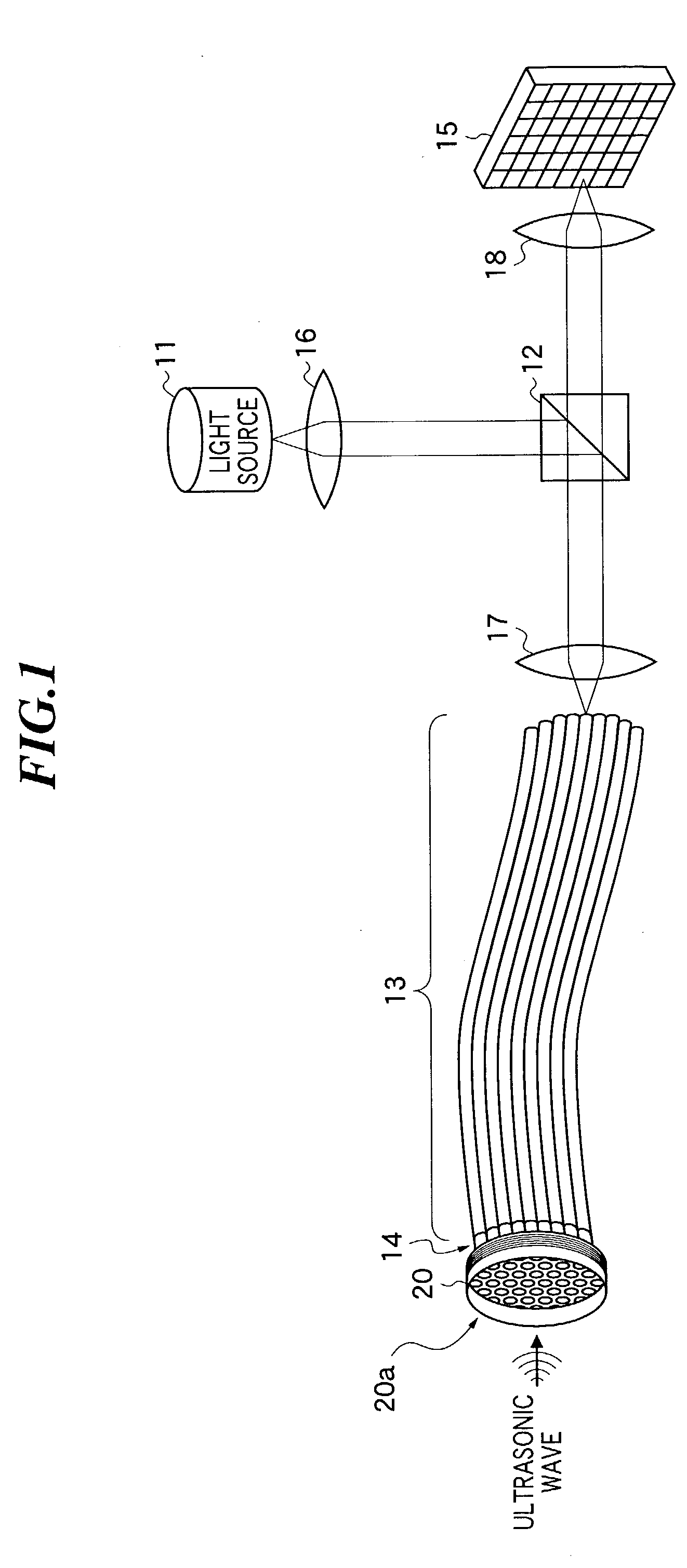
[0040] FIG. 1 is a diagram showing ultrasonic receiving apparatus according to the present invention. The ultrasonic receiving apparatus comprises a light source 11, a beam separator 12, an optical transmission path 13, a collimating portion 14, an ultrasonic detecting element 20 for modulating light on the basis of a received ultrasonic wave, a photodetector 15, and focussing systems 16-18.

[0041] As for the light source 11, a tunable LD (laser diode) having a predetermined band (for example, 1.55 .mu.m) is used. The beam separator 12 comprises a half mirror, a light circulator, a polarizing beam splitter and so on. The beam separator 12 reflects incident light, which enters from a first direction, to a second direction, and allows the reflected light returned from the second direction to pass through to a third direction which is different from the first direction. In the first embodiment, a half mirror is used as the beam separator 12. The half mirror reflects the incident light i...

second embodiment

[0073] since the multi-layered film is formed directly on the collimator lens, the strength of the connecting portion between the collimator lens and the ultrasonic detecting element is increased. Further, since the reflection of the ultrasonic wave at the connecting portion is further reduced, the ultrasonic wave can be easily released into the fiber portion resulting in an effective prevention of the multiple reflection.

[0074] Next, referring to FIG. 6, an ultrasonic receiving apparatus according to a third embodiment of the present invention will be described below. The ultrasonic receiving apparatus as shown in FIG. 6 has a backing portion 50 in place of the optical transmission path 13 and the collimating portion 14 as shown in FIG. 1. The constitution other than the above is the same as that of the first embodiment.

[0075] The backing portion 50 includes an optical transmitting portion 51 that transmits the light used for detection and a cover portion 52 for attenuating the ul...


PUM


Abstract

In a photo-detection type ultrasonic receiving apparatus, the image quality of ultrasonic image has been enhanced by reducing multiple reflection of the ultrasonic wave. The ultrasonic receiving apparatus according to the present invention includes an ultrasonic detecting element for modulating light on the basis of a received ultrasonic wave, a backing portion directly or indirectly connected to the ultrasonic detecting element propagating the ultrasonic wave to be applied to the ultrasonic detecting element, the backing portion having optical transmissibility and guiding the light used for detecting ultrasonic wave, and a photoelectric conversion unit that detects the light output from the ultrasonic detecting element.

Description

[0001] 1. Field of the Invention[0002] The present invention relates to an ultrasonic receiving apparatus for receiving ultrasonic waves, and further to an ultrasonic imaging apparatus to be used for medical diagnosis or nondestructive inspection by receiving ultrasonic waves using such an ultrasonic receiving apparatus.[0003] 2. Description of a Related Art[0004] Conventionally, in an ultrasonic imaging apparatus, generally a one-dimensional sensor array using a piezoelectric element including a piezoelectric ceramic represented by PZT (Pb(lead) zirconate titanate) or a macromolecule piezoelectric element such as PVDF (polyvinyl difluoride) has been used as an element (vibrator) for transmitting and receiving ultrasonic waves. Two-dimensional images in plural cross sections of an object to be inspected are obtained while mechanically shifting a one-dimensional sensor array as described above, and further, by synthesizing these two-dimensional images, a three-dimensional image is ob...

Claims


Application Information

Patent Timeline
Patent Type & Authority Applications(United States)
IPC IPC(8): G01H9/00
CPCG01H9/004
Inventor OGAWA, EIJI
Owner FUJIFILM HLDG CORP
Why Eureka
Try Eureka