Two-cycle combustion engine having two-staged piston

Inactive Publication Date: 2003-10-16
KAWASAKI HEAVY IND LTD
View PDF5 Cites 12 Cited by
  • Summary
  • Abstract
  • Description
  • Claims
  • Application Information

AI Technical Summary

Problems solved by technology

Accordingly, the conventional two-cycle combustion engine is susceptible to a problem in that a portion of the air-fuel mixture supplied into the combustion chamber tends to flow outwardly through an exhaust port together with the combustion gas, that is, susceptible to a so-called blow-off phenomenon.
It has, however, been found that the first mentioned two-cycle combustion engine disclosed in the Japanese Laid-open Patent Publication No. 5-118225 has a problem in that it requires a mechanism for driving the intake valve for selectively opening or closing the intake port, through which the air-fuel mixture can be introduced into the combustion chamber, by means of a cam shaft or a crankshaft.
In addition, the first mentioned two-cycle combustion engine requires a carburetor for supplying the air-fuel mixture into the pump chamber, an air cleaner for supplying an air into the crank chamber and the intake valve for selectively opening or closing the intake port through which the air-fuel mixture can be supplied from the pump chamber into the combustion chamber to be disposed having been spaced a distance from each other, resulting in complication in structure and increase in cost.
Yet, since the air-fuel mixture is introduced into the combustion chamber d

Method used


Image

  • Two-cycle combustion engine having two-staged piston
  • Two-cycle combustion engine having two-staged piston
  • Two-cycle combustion engine having two-staged piston

Examples


third embodiment

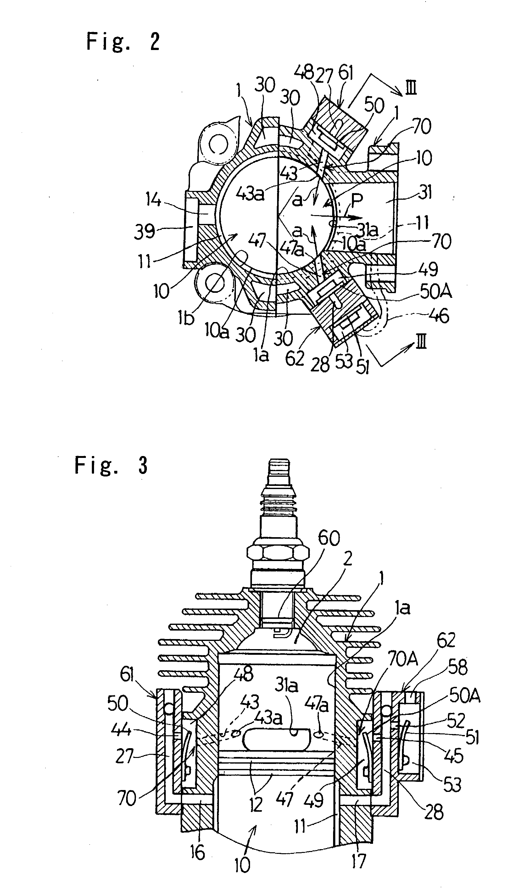
[0058] In this third embodiment shown in FIGS. 5 and 6A to 6C, connecting paths 65 and 66 are defined in the cylinder block 1 so as to extend from the auxiliary chamber 11 to the outside in a radial direction as shown in FIG. 6A and are positioned at respective locations opposite sides of the exhaust passage 31 in the cylinder block 1 and spaced about 45.degree. from the exhaust passage 31 about the longitudinal axis C of the cylinder bore in the cylinder block 1 as shown in FIG. 5. In addition, relatively large recesses communicated with the associated connecting paths 65 and 66 are formed at respective locations outside the connecting paths 65 and 66 in the cylinder block 1, and one of those recesses is covered by a lid member 67 to define a pressure accumulating chamber 63 serving concurrently as a third valve chamber, while the other of the recesses is covered by a valve chamber defining member 68 to define a pressure accumulating chamber 64 serving concurrently as a third valve...

first embodiment

[0060] The valve chamber defining member 68 referred to above is closed by a lid member 74 with a fourth valve chamber 73 consequently defined between it and the lid member 74. This fourth valve chamber 73 is in communication with the pressure accumulating chamber 64 through a discharge port 69 that is adapted to be selectively opened or closed by a fourth check valve 51A accommodated within the fourth valve chamber 73. The pressure at which this fourth check valve 51A opens is so chosen as to be equal to or higher than the pressure inside the combustion chamber 2 at the time the scavenge outlet port 30a opens during the descending motion of the two-staged piston 10. Accordingly, when this fourth check valve 51A opens, the air flowing into the fourth valve chamber 73 can be discharged either to the outside of the combustion engine through the discharge mouth 58 or into the exhaust passage 31 through an exhaust tube (not shown). Also, as shown in FIG. 6A, the injection ports 43a and ...

fourth embodiment

[0065] In the two-cycle combustion engine a valve chamber defining member 76 is fixed to the cylinder block 1 at a location radially outwardly of the auxiliary chamber 11 to define a single pressure accumulating chamber 75. This pressure accumulating chamber 75 is communicated with the auxiliary chamber 11 through a connecting path 77 extending in a direction perpendicular to the longitudinal axis C of the cylinder bore to form a part of each of the injection passages 70 and 70A. This connecting path 77 is selectively opened or closed by the third check valve 50 fitted inside the pressure accumulating chamber 75 that is positioned below the exhaust passage 31 in the cylinder block 1 as shown in FIG. 7B.

[0066] Air outlet ports 83 and 84 are defined on opposite sides of the pressure accumulating chamber 75 and are communicated with the injecting guide paths 43 and 47, as shown in FIG. 7A, through connecting passages 85 and 86 each in the form of a connecting pipe, respectively. The i...


PUM


Abstract

To provide a two-cycle combustion. engine having a two-staged piston, which is simple in structure and inexpensive and in which an undesirable blow-off phenomenon of the air-fuel mixture can be avoided effectively, the two-cycle combustion engine includes a cylinder block <bold>1 </highlight>having a two-staged cylinder bore defined therein and having a reduced diameter bore portion <bold>1</highlight><italic>a </highlight>and a large diameter bore portion <bold>1</highlight><italic>b, </highlight>and a two-staged piston <bold>10 </highlight>having a reduced diameter piston portion <bold>10</highlight><italic>a </highlight>and a large diameter piston portion <bold>10</highlight><italic>b </highlight>and drivingly accommodated within the two-staged cylinder bore. An annular auxiliary chamber <bold>11 </highlight>is defined between the two-staged cylinder bore and the reduced diameter piston portion <bold>10</highlight><italic>a </highlight>of the two-staged piston. The two-cycle combustion engine also includes an air-fuel mixture passage <bold>21 </highlight>for introducing the air-fuel mixture into a crank chamber, an air passage <bold>24 </highlight>for introducing an air into the auxiliary chamber <bold>11, </highlight>a scavenge passage <bold>30 </highlight>for supplying the air-fuel mixture within the crank chamber <bold>29 </highlight>into a combustion chamber, and injection passages <bold>70 </highlight>and <bold>70</highlight>A for injecting the air within the auxiliary chamber <bold>11 </highlight>into the combustion chamber <bold>2. </highlight>

Description

[0001] 1. Field of the Invention[0002] The present invention generally relates to a two-cycle combustion engine suitable for use as a power plant for a compact rotary machine such as a brush cutter and, more particularly, to the two-cycle combustion engine of a structure having a two-staged piston drivingly accommodated within a corresponding two-staged cylinder bore.[0003] 2. Description of the Related Art[0004] The two-cycle combustion engine is generally of a design in which an air-fuel mixture introduced into a crank chamber is supplied into a combustion chamber to scavenge a combustion gas within the combustion chamber. Accordingly, the conventional two-cycle combustion engine is susceptible to a problem in that a portion of the air-fuel mixture supplied into the combustion chamber tends to flow outwardly through an exhaust port together with the combustion gas, that is, susceptible to a so-called blow-off phenomenon. In view of this, in order to avoid the blow-off phenomenon, ...

Claims


Application Information

Patent Timeline
IPC IPC(8): F02B33/14F02B1/04F02B25/16F02B25/20F02B25/22F02B33/04F02B33/30F02B33/44F02B63/02F02B75/02F02B75/16
CPCF02B1/04F02B25/22F02B33/04F02B2075/025F02B33/30F02B63/02F02B75/16F02B33/14
Inventor YUASA, TSUNEYOSHIYAMANE, YOSHIROKOBAYASHI, MASANORI
Owner KAWASAKI HEAVY IND LTD
Why Eureka
Try Eureka