Method and installation for densifying porous substrates by chemical vapour infiltration

a technology of densification and chemical vapour, which is applied in the direction of chemical vapor deposition coating, coating, metallic material coating process, etc., can solve the problems of reducing the working volume available in the loading zone, reducing reducing the efficiency of the process. , to achieve the effect of improving the productivity of such ovens, without deterioration

Inactive Publication Date: 2003-11-06
SION ERIC +2
View PDF35 Cites 10 Cited by
  • Summary
  • Abstract
  • Description
  • Claims
  • Application Information

AI Technical Summary

Benefits of technology

[0010] The object of the invention is to propose a method of densification by chemical vapour infiltration which makes it possible to obtain a temperature gradient which is very small throughout the loading zone, but without requiring a large volume for the zone that heats the reactive gas, and thus without deteriorating, and possibly even improving the productivity of such ovens.
[0018] Preheating the reactive gas outside the loading zone enables the heating zone situated within the oven to be more effective in bringing the reactive gas to the desired temperature as soon as it penetrates into the substrate loading zone.
[0019] When infiltration is performed at a temperature greater than 900.degree. C., the reactive gas is preheated prior to entering into the oven so that on entering the oven it is at a temperature which is preferably not less than 200.degree. C. Nevertheless, it is preferable for the temperature to which the gas is preheated not to exceed 900.degree. C., or even 600.degree. C., in order to avoid any unwanted deposits due to the precursor(s) being transformed prior to penetrating into the oven, and in order to make it possible to use relatively ordinary materials for the pipework feeding the oven with preheated reactive gas and for components such as valves and gaskets mounted in said pipework.

Problems solved by technology

The Applicants have found that the presence of a zone for heating the reactive gas does not always give the desired result.
Nevertheless, for given total volume of the oven, that would reduce the working volume available in the loading zone.
Unfortunately, chemical vapour infiltration processes require large amounts of industrial investment and they are very lengthy to perform.

Method used


Image

  • Method and installation for densifying porous substrates by chemical vapour infiltration
  • Method and installation for densifying porous substrates by chemical vapour infiltration
  • Method and installation for densifying porous substrates by chemical vapour infiltration

Examples


Embodiment Construction

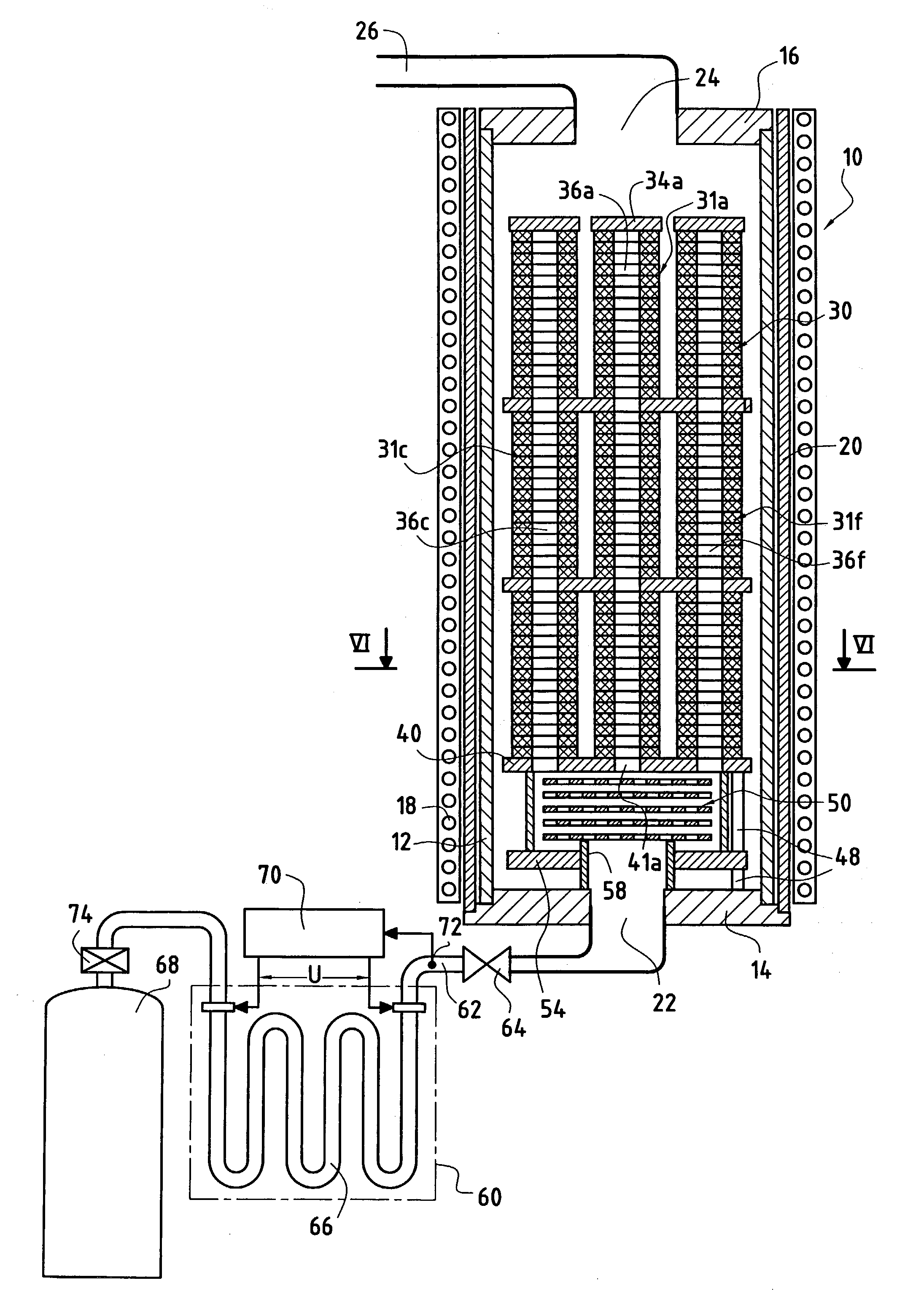
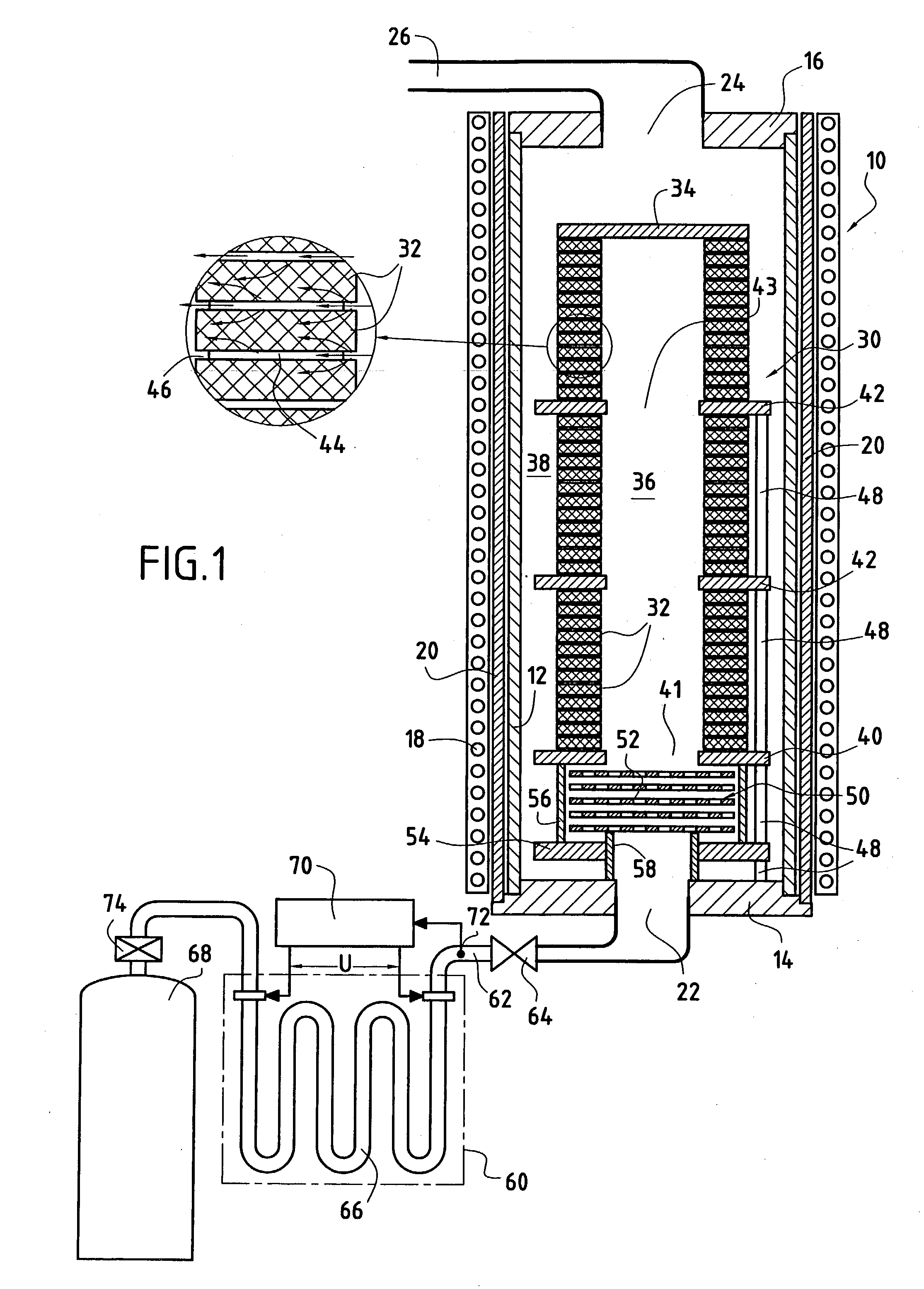
[0035] Implementations of the method and embodiments of the installation of the invention are described below in the context of an application to densifying annular porous substrates. The latter may constitute carbon fiber preforms or pre-densified blanks for making brake disks out of C / C composite material, the pre-densified blanks being obtained by pre-densification of performs by chemical vapour infiltration or by liquid (resin) impregnation followed by carbonization. Such brake disks are commonly used for aircraft landing gears and for racing cars.

[0036] FIG. 1 is a diagram showing an oven 10 defined by a cylindrical side wall 12, a bottom wall 14, and a top wall 16. The wall 12 constitutes a secondary transformer circuit or susceptor, e.g. being made out of graphite, and it is coupled with a primary transformer circuit or induction coil 18 situated outside the oven, with insulation 20 interposed between them. The oven is heated by the susceptor 12 when electricity is fed to the...


PUM

PropertyMeasurementUnit
temperatureaaaaaaaaaa

Abstract

An installation for densification of porous substrates by CVI comprises an oven, a zone for loading substrates in the oven, means for heating substrates loaded in the loading zone, at least one inlet for admitting reactive gas in the oven, and at least one gas heating zone situated in the oven between the reactive gas inlet and the loading zone. At least one gas preheating device is located outside the oven and is connected to the gas inlet so as to preheat the reactive gas before it enters the oven.

Description

[0001] This application is a divisional application under .sctn.1.53(b) of prior application Ser. No. 10 / 034,848 filed Dec. 26, 2001, entitled: METHOD AND INSTALLATION FOR DENSIFYING POROUS SUBSTRATES BY CHEMICAL VAPOUR INFILTRATION.[0002] The invention relates to densifying porous substrates by chemical vapour infiltration (CVI).[0003] The field of application of the invention is that of making parts out of thermostructural composite material, i.e. out of a composite material that not only possesses mechanical properties that enable it to be used for making structural parts, but that also has the ability to conserve these properties at high temperatures. Typical examples of thermostructural composite materials are carbon / carbon (C / C) composites having a reinforcing fabric of carbon fibers densified by a pyrolytic carbon matrix, and ceramic matrix composites (CMCs) having a reinforcing fabric of refractory fibers (carbon or ceramic) densified by a ceramic matrix.[0004] A well known ...

Claims


Application Information

Patent Timeline
Patent Type & Authority Applications(United States)
IPC IPC(8): C04B35/83C04B35/80C23C16/04C23C16/26C23C16/42C23C16/44C23C16/455
CPCC04B35/83Y10S427/10C23C16/4557C23C16/045C04B41/45
Inventor SION, ERICBAUDRY, YVANDELPERIER, BERNARD
Owner SION ERIC
Why Eureka
Try Eureka