Optical security system

a security system and optical technology, applied in the field of optical security systems, can solve the problems of increasing the cost of the system, increasing the cost of the security system, and increasing the security area, so as to achieve convenient installation and disassembly, and simple construction. , the effect of reliable operation

Inactive Publication Date: 2003-11-06
MULTIMETRIXS
View PDF0 Cites 18 Cited by
  • Summary
  • Abstract
  • Description
  • Claims
  • Application Information

AI Technical Summary

Benefits of technology

0017] It is an object of the invention to provide an optical or a combined optical-electromagnetic security system which is simple in construction, reliable in operation, composed of components having miniature dimensions, easy to install and dismantle, contains self-contained module-type components, can be easily transferred to another location and quickly remotely activated or deactivated. It is another object to provide an optical or combined optical-electromagnetic security system that can be quickly and frequently coded and decoded. Another object is to provide an optical or c

Problems solved by technology

The larger is the area, the greater is the perimeter, the more expensive is the system, and the more difficult is to provide reliable protection.
An increase in the secured areas is associated not only with an increase in expenses, but also with technical problems, since surveying of large areas is limited by technical capacities of existing light sources, transmitters, receivers, and data processing devices.
Another problem is a significant time required for assembling and disassembling of existing security systems, e.g., for temporary use.
Such a problem may occur, when it is necessary to prevent temporary, e.g., seasonal, penetration of people into an avalanche zone, or a fire-hazardous zone, or the like.
For example, security systems intended for protection against penetration into a building through windows or doors will obviously be unsuitable for surveying an open area with a large perimeter.
A main disadvantage of the system described

Method used


Image

  • Optical security system
  • Optical security system
  • Optical security system

Examples


Embodiment Construction

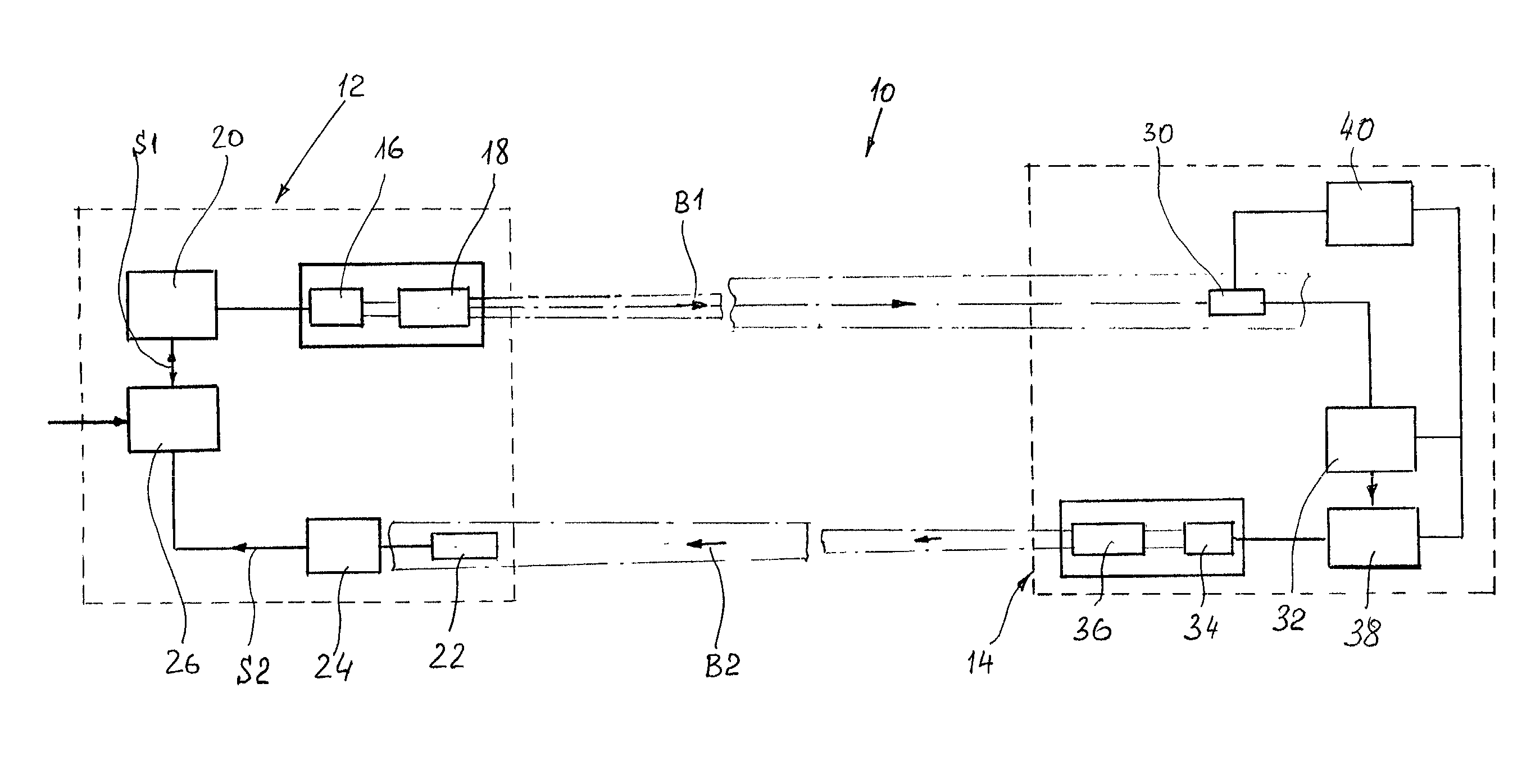
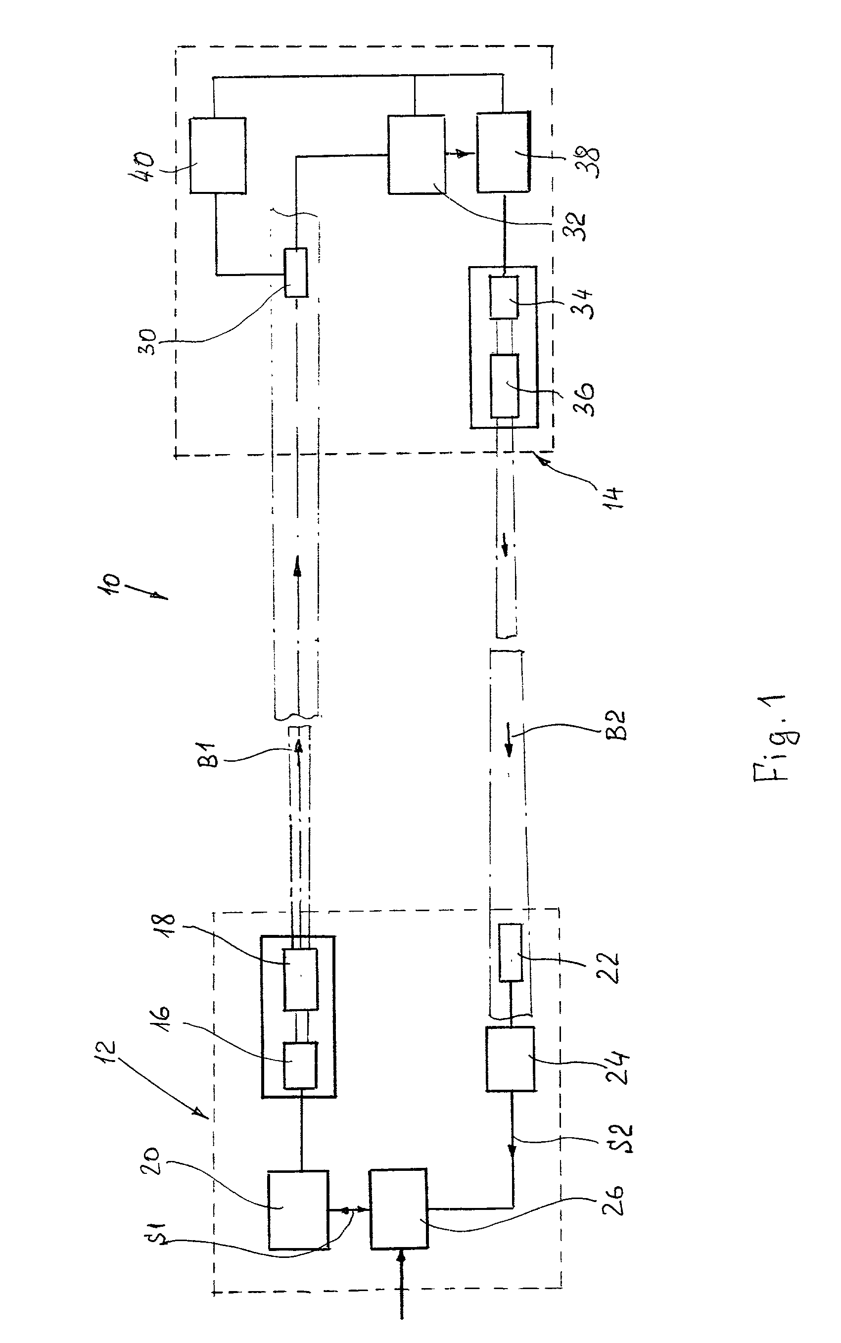
[0024] An optical security system made according to one embodiment of the invention is shown in FIG. 1. This optical security system, which in general is designated by reference numeral 10, consists of a first transmitting-receiving unit 12 located in point of the zone to be secured and a second transmitting-receiving unit 14 located remotely from the first unit 12 at a distance that spans the entire area to be surveyed with the security system 10.

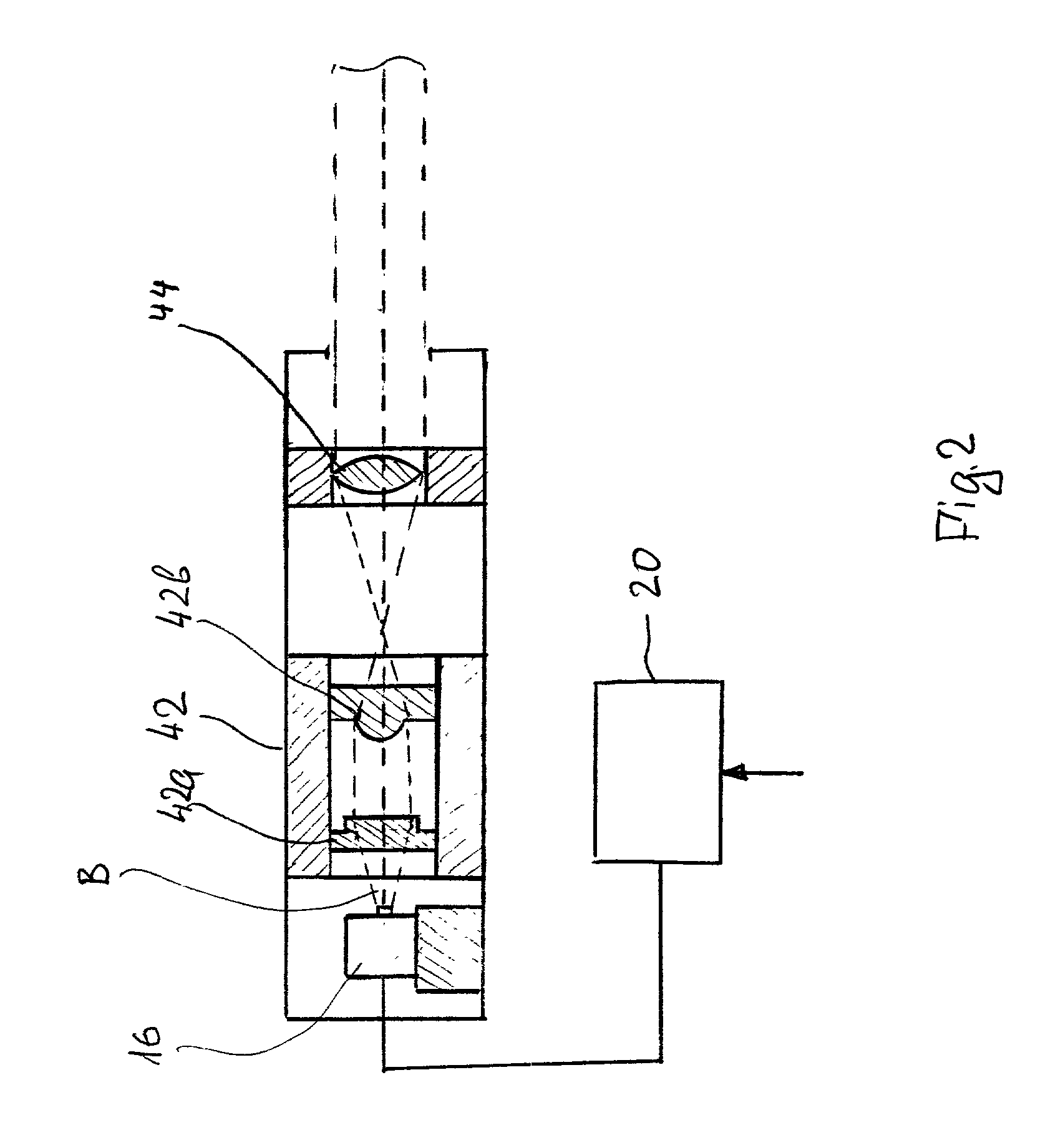
[0025] The transmitting-receiving unit 12 consists of the following components: a signal source, in this case a laser diode 16 with an optical beam collimator 18 located in front of the laser diode emitter (not shown); a laser driver 20 for ignition of the laser diode 16 and for maintaining the laser diode 16 in operation mode; a signal receiving sensor 22 with a signal amplifier 24 for receiving and amplifying external optical signals; a central processing unit 26 which is connected to both the laser driver 20 and the signal amplifier 24 ...


PUM


Abstract

According to one embodiment of the invention, the optical security system consists of a first laser beam generation and feedback signal receiving station on one end of the security zone and a second laser beam receiving and feedback signal transmitting station on the other end of the security zone. The first station consists of a laser source that generates a modulated low-divergence laser beam and a first optical signal receiver. The second station consists of a second optical signal receiver that receives the aforementioned modulated low-divergence laser beam emitted from the laser source and a feedback optical signal transmitter which is connected to the aforementioned second optical signal receiver via a signal processing unit which codes the received signal and forms it into a feedback signal to be sent to the first optical signal receiver of the first station from the transmitter of the second station. In the system of the second embodiment the feedback signals are in the form of IR, MW, or RF signals. The intruder is detected by comparing changes in the codes of direct and return signals.

Description

[0001] The present invention relates to a security system, in particular to an optical security system based on the principle of detecting intentional or unintentional intruders, including human beings, animals or moving objects in general, into unauthorized or forbidden areas, such as a military weapon test ground, a hazardous area, e.g., a contaminated zone, or the like.[0002] It is often required to prevent penetration of unauthorized individuals to such areas as shooting ranges, state borders, hazardous zones, test grounds, or the like.[0003] The problems become more aggravated when it is necessary to provide protection of large areas, i.e., areas with large perimeters. The larger is the area, the greater is the perimeter, the more expensive is the system, and the more difficult is to provide reliable protection. An increase in the secured areas is associated not only with an increase in expenses, but also with technical problems, since surveying of large areas is limited by tec...

Claims


Application Information

Patent Timeline
IPC IPC(8): G08B13/183G08B29/18
CPCG08B29/183G08B13/183
Inventor GREBENSHCHIKOV, IGOR A.POVAROV, ALEXANDERMARGULIS, DAVID
Owner MULTIMETRIXS
Why Eureka
Try Eureka