
Liquid heating method and apparatus particularly useful for vaporizing a liquid condensate from cooling devices

Inactive Publication Date: 2003-11-06
A T C T ADVANCED THERMAL CHIP TECH
View PDF5 Cites 69 Cited by
  • Summary
  • Abstract
  • Description
  • Claims
  • Application Information

AI Technical Summary

Benefits of technology

[0010] According to further features in the preferred embodiment of the invention described below, the heating plate is heated by a positive temperature coefficient (PTC) heating device, particularly a PTC thermistor, in which the electrical resistance increases with an increase in current such as to effect self-regulation with respect to temperature, thereby obviating the need for costly temperature sensors and control circuitry.
[0017] As will be described below, a number of important advantages are attainable particularly where the heating devices are positive temperature coefficient heaters, including: minimizing power consumption; obviating the need for temperature sensors and complicated electronic controls; long useful life since the PTC heating devices are generally oxides and are therefore not affected by oxidation; substantial elimination of the possibility of over-heating since the PTC device is fixed to a set temperature; high rate of heating and cooling; substantial non-sensitivity to variations in the supply voltage; low cost; and / or low weight.

Problems solved by technology

If such condensed water is not immediately removed, it will freeze and thereby reduce the operating efficiency of the heating device.
However, there are many situations wherein removal of water condensate in such a manner is not possible or practical.
Another known technique for removing water condensate is by vaporizing the water condensate, but such known techniques generally require considerable electrical power consumption and / or relatively complicated control systems.
However, PTC thermistors have number of drawbacks which have heretofore limited their use in heating applications.
Thus, permanent connections to PTC thermistors, such as by soldering or welding, generally have short service lives because the differences in thermal coefficients of expansion at the connections produce strains and cracks during heating / cooling cycles.
In addition, thermal gradients in PTC thermistors, due to non-uniform heat transfer or exposure to air or gas flow, create a "pinch effect" which reduces heat generation efficiency and service life.
Further, high local electrical field strengths due to sharp edges or ridges may trigger an electric arc that can destroy the thermistor.
However, in both cases, the disclosed devices have thermal resistance between the PTC elements and the heat exchange members that reduces their heat transfer efficiency, and thereby their power output.
In addition, such devices have the additional disadvantage of not being fully immersible and / or of requiring channels for the liquid through heat transfer members, which complicates their construction and integration into liquid systems to be heated.

Method used


Image

  • Liquid heating method and apparatus particularly useful for vaporizing a liquid condensate from cooling devices
  • Liquid heating method and apparatus particularly useful for vaporizing a liquid condensate from cooling devices
  • Liquid heating method and apparatus particularly useful for vaporizing a liquid condensate from cooling devices

Examples


Embodiment Construction

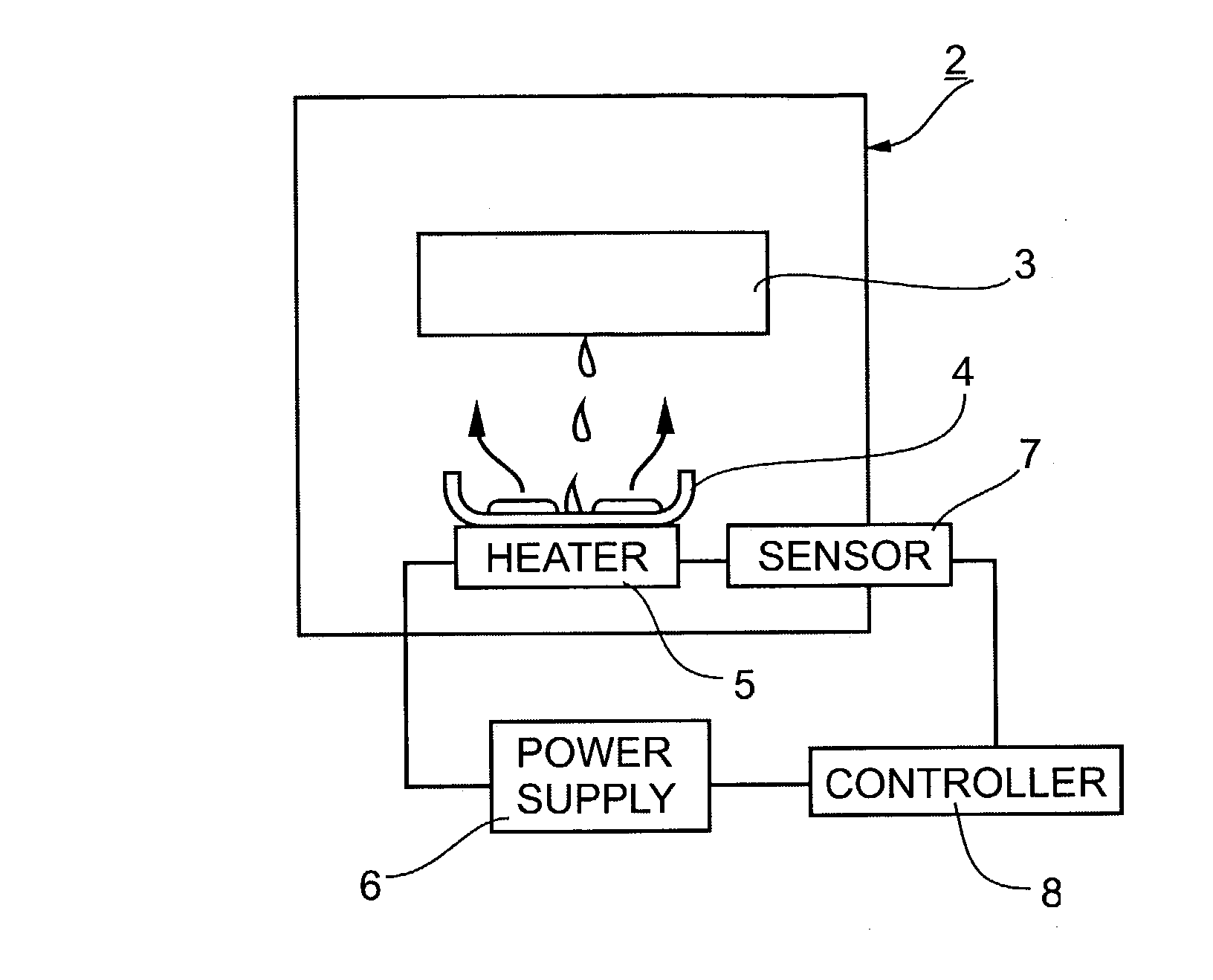
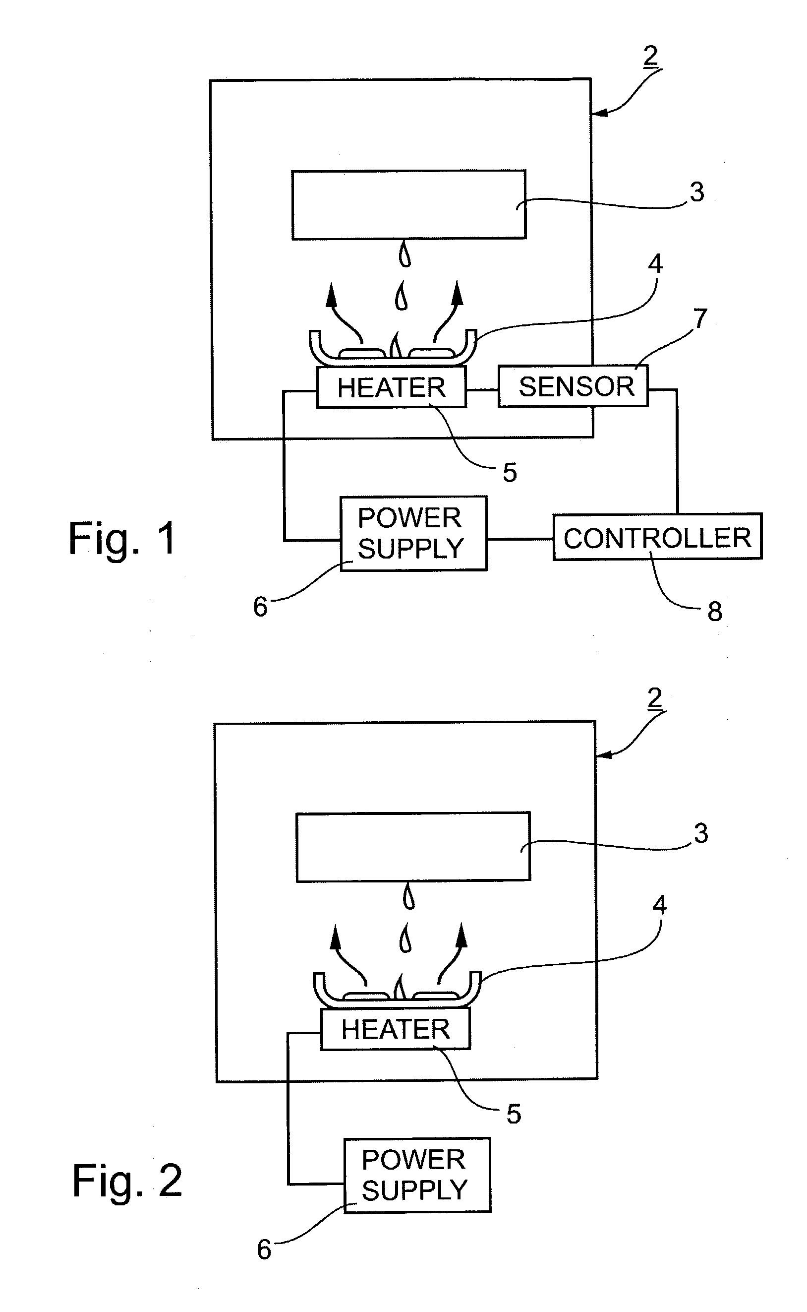
[0039] With reference first to FIG. 1, there is schematically illustrated a cooling device, such an air conditioner 2, which produces, during its normal operation, a water condensate by the cooling of the water within the atmosphere in contact with the cooling surface of the device. This water condensate is directed to, and / or collected in, a collector schematically shown at 3.

[0040] In a conventional air conditioner, the condensate is removed via a drain tube leading to the atmosphere. According to the present invention however, the condensate is removed by vaporization via a heating plate 4 wetted by the water condensate, and heated by heater device 5 energized by an electrical power supply 6. As will be described more particularly below, the heating plate 4 is heated to a predetermined high temperature, above the boiling point of the water condensate. This predetermined high temperature may be preset and, in the embodiment illustrated in FIG. 1, is thereafter continuously sensed ...


PUM

PropertyMeasurementUnit
Temperatureaaaaaaaaaa
Electrical resistanceaaaaaaaaaa
Electrical conductoraaaaaaaaaa

Abstract

A method and heating device for heating a liquid, particularly useful for removing liquid condensate from cooling devices, by wetting a heating plate with the liquid and controlling the electrical power supply to maintain the heating plate at a the predetermined temperature above the boiling point of the liquid, such that when the heating plate is not wetted by the liquid, the electrical power supply to the heating plate is automatically maintained at a relatively low value, but as soon as the heating plate is wetted by the liquid, the electrical power supplied to the heating plate is automatically increased until the liquid is completely evaporated. The heating plate is heated by one or more PTC thermistors in which the electrical resistance increases with temperature to automatically maintain the predetermined temperature. Besides evaporating liquid condensate, the heating device is described for use in many other applications including steam generation, space heating and plastic molding.

Description

[0001] The present application is related to Provisional Applications (1) No. 60 / 226,666 filed Aug. 22, 2000, (2) No. 60 / 228,416 filed Aug. 29, 2000 (3) No. 60 / 229,050 filed Aug. 31, 2000; (4) No. 60 / 229,049, filed Aug. 31, 2000 and (5) No. 60 / 240,834 filed Oct. 17, 2000, and claims the priority dates of those applications.FIELD AND BACKGROUND OF THE INVENTION[0002] The present invention relates to a method, to an electrical heating device, and to apparatus for heating a liquid. The invention is especially useful for vaporizing a liquid condensate produced during the operation of cooling devices, but is also useful for heating or vaporizing water in many other applications, some of which are described below for purposes of example.[0003] The operation of cooling devices, such as air conditioners, refrigerators, and other types of heat pump machines, is generally accompanied by a condensation of water from the atmosphere. If such condensed water is not immediately removed, it will fr...

Claims


Application Information

Patent Timeline
IPC IPC(8): A47J27/04A47J27/16A47J31/54F22B1/28F24F13/22F25D21/14H05B3/24H05B3/50
CPCA47J27/04A47J27/16A47J31/54F22B1/287H05B2203/02F24F13/222F25D21/14H05B3/24H05B3/50F24F5/0042
Inventor GOLAN, GADY
Owner A T C T ADVANCED THERMAL CHIP TECH
Learn More